Title: Micro
Doc No.: 018-1000-02
Description: Emergency Lighting Inverter User’s Manual Date: 07/26/2016
Rev: NR
1.877.DSPM.POWERPhone : 1.877.377.6769-
909.930.3335Fax:
www.dspmanufacturing.com
Website:
techsupport@dspmanufacturing.com
E-Mail:
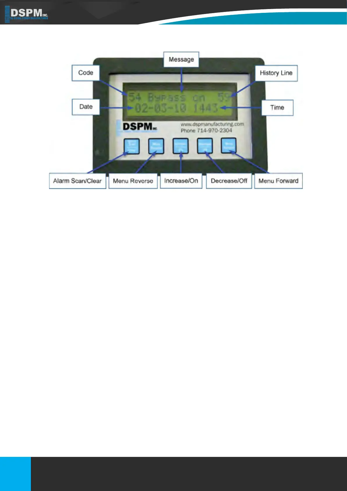
Figure 13
7. DISPLAYS
7.1. FRONT PANEL DESCRIPTION
7.2. HISTORY LOG KEY
7.1.1. – Code: Indicated which alarm has been triggered. Use the History Log Key Table (on the following page/(s) to
help nd the description of the alarm.
7.1.2. Message: Indicates the message for the alarm that was triggered.
7.1.3. History Line: Indicates the line that an event has been recorded on.
7.1.4 – Date: Indicates the date that the alarm was triggered.
7.1.5. Time: Indicates what time the alarm was triggered; the time is shown in military time.
7.1.6. Alarm Scan / Clear: By holding down this button you can scroll the history log. By pressing this button you can
clear.
7.1.7. Menu Reverse: To scroll menu left.
7.1.8. Increase / On: To change setting up.
7.1.9. Decrease / Off: To change setting down.
7.1.10. Menu Forward: To scroll menu right.
The History Log is used to record certain events that reect the status and operating mode of the unit. The unit has
the capability of logging up to 64 lines/events (00 through 63). After 00 is displayed, the system will cycle around to 63.
After 64 events are logged, the system will start recording again at 00. The Log is read by pressing or holding down the
Alarm Scan button. The most recent event being displayed rst. Each time the button is pressed one log event is read
in sequential order. The following table is a list of possible faults that can be displayed on the LCD Display.
34
Title: Three Phase 208 or 208Y/120Vac
Doc No.: 018-6000-00
Description: Emergency Lighting Inverter User’s Manual
Rev: NR
Date: 08/12/2022
Phone :
Website:
E-Mail:
Fax:
1.877.DSPM.POWER-1.877.377.6769
1.877.DSPM.POWER-1.877.377.6769
www.dspmanufacturing.com
techsupport@dspmanufacturing.com