1.877.377.6769
Fax: 909.930.3335
Plus
074-2000-00
--
Online Emergency Lighting Inverter Maintenance Manual
2
1
5 - 9
3
4
10
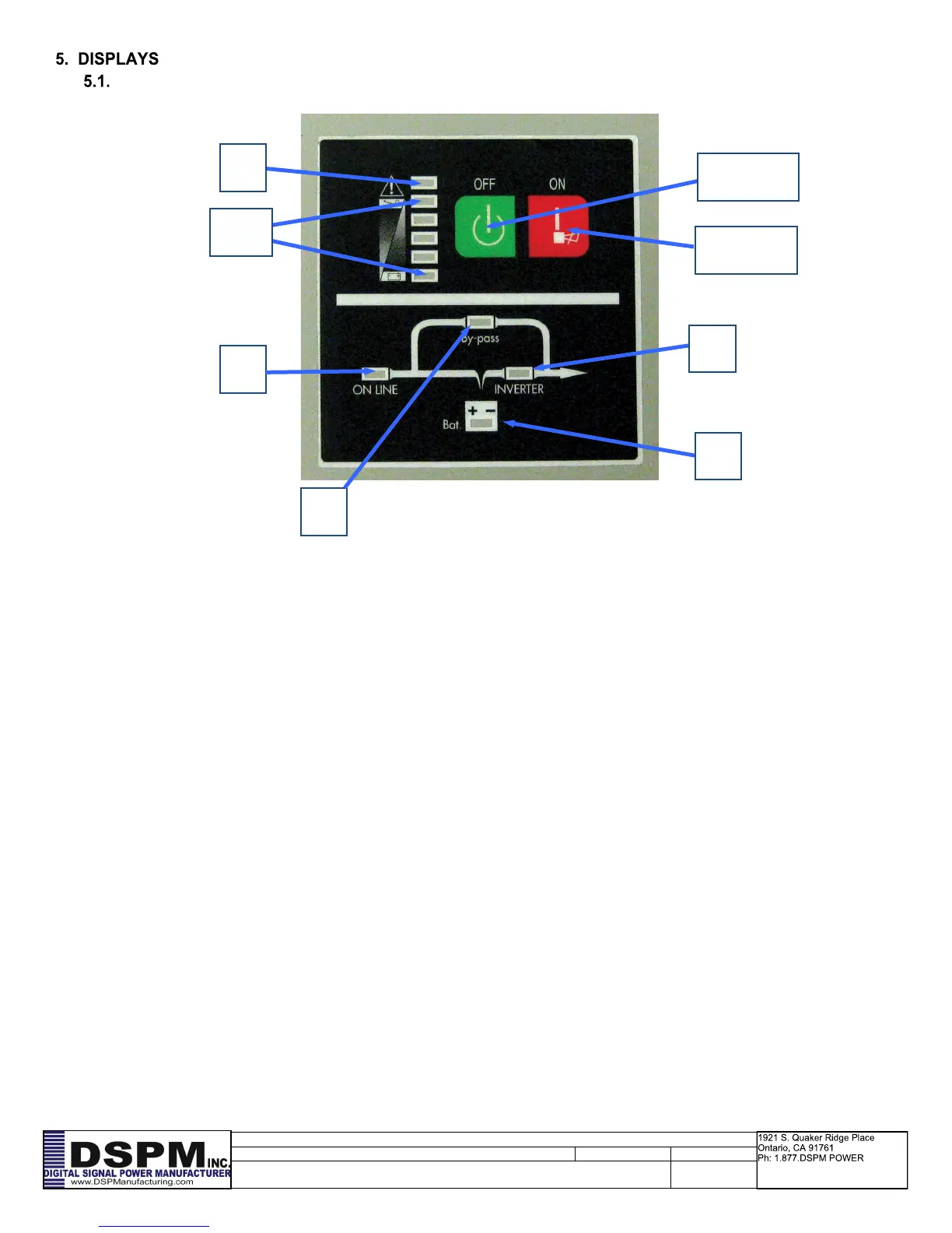
OFF Key
ON Key
5.1.1. To indicate the AC Power is applied to the system input. In case this LED blinks, it
means the main AC source is out of tolerance.
5.1.2. To indicate the load is powered via the bypass.
5.1.3. To indicate the system is in battery backup mode when the building source power
has failed.
5.1.4. To indicate the system is powered through the inverter
5.1.5-9.
Number 5 and 8 LED’s are green colored and Number 9 (used as a Warning LED for overload or
battery low) is yellow.
Number 5 to 8 LED’s show the load % of the system if the main power is available (in normal opera-
tion). Each of the green LED’s will indicate a % of the power level for the rating of the system.
Depending on unit size the LED’s 5 to 9 may not indicate the actual load.
In the battery operation, the LED’s indicate the capacity (%) of the batteries run time remaining, As
the batteries are depleted the LED’s will extinguish from left to right. When LED number 9 is only
lighted then there is 0-25% left on the battery run.
5.1.10. To indicate that the Emergency Lighting Inverter System is in a fault condition be-
cause of inverter shutdown or over temperature condition.
5.1.11. This button needs to be pushed to turn the emergency lighting inverter off.
5.1.12. This button needs to be pushed to turn the emergency lighting inverter on.