RPT-5 Tester – User manual 5
battery symbol ( ). If the symbol is visible next to it, it means that the Bluetooth
module is active and it is possible to communicate with a compatible device mobile.
After starting, the device will go to the main menu. Use [▲] and [▼] buttons to select a
chosen function and[OK] to confirm.
The list of available menu items is discussed in the following paragraphs.
3.1 Sensor test
1. Connect in parallel to the pressure sensor circuit using an adapter with a sensor
connector or with a needle probe. Connect the device with the adapter attached to the
sensor.
2. Choose the type of system:
• CR (Common Rail) – direct diesel injection in diesel engines.
• GDI (Gasoline Direct Injection) – direct gasoline injection (FSI, SIDI) in spark-
ignition engines.
3. Select the system variant (for the Common Rail system):
• Bosch/Denso – sensor with a scaled output in the range: 0,5 – 4,5V
• Denso – sensor with a scaled output in the range: 1 – 4,2V
4. Select the range of the sensor - the options available vary depending on the selected
system.
After selecting the Other option, you can manually set the sensor range using the [ ▲]
and [▼] buttons.
5. Turn on the sensor supply (ignition). After the signal is detected, the tester will
automatically recognize the pinout and start displaying pressure.
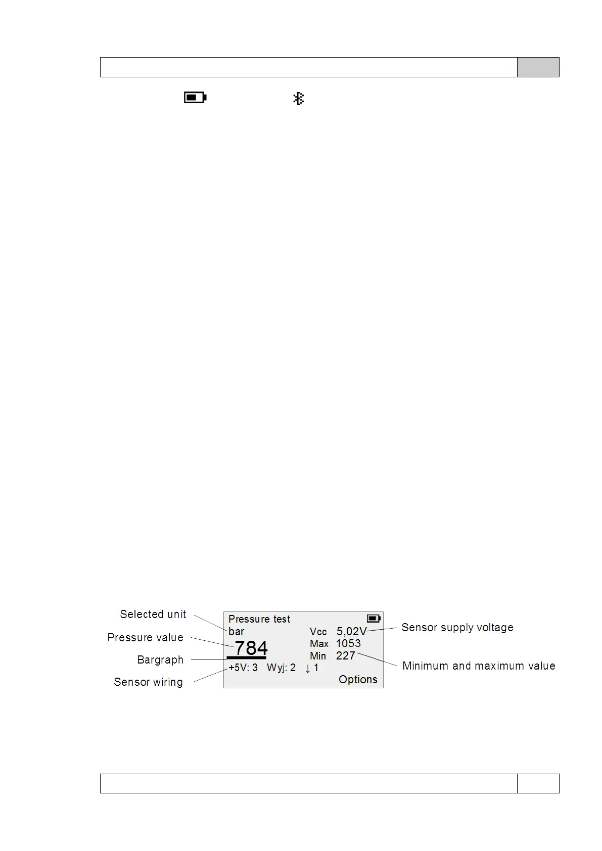
Pressure test screen:
The numbering of signals in the pinout system is consistent with the pin numbers in the
connector or with the numbers of the probes for connecting the needle probes.
© DeltaTech Electronics 2024 Ver.2.1