13
049
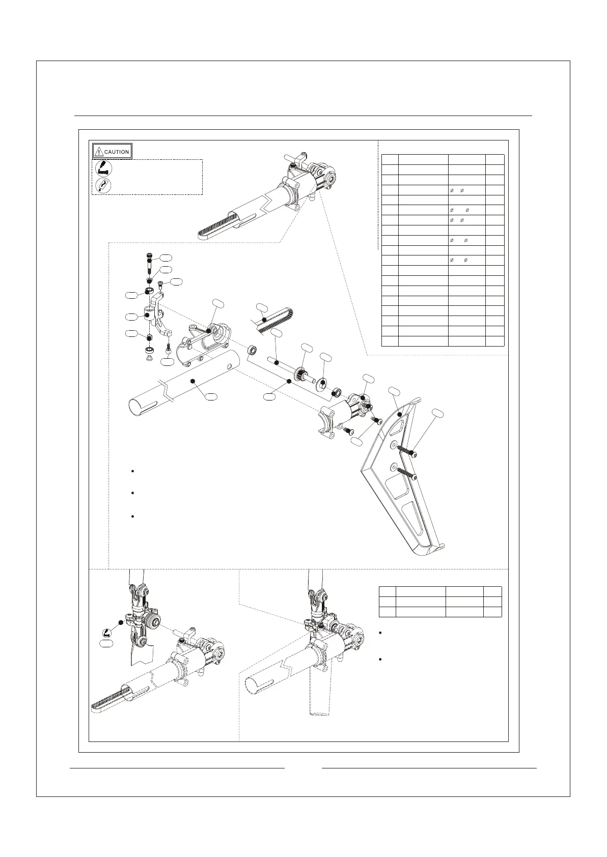
Install the screws into the tail rotor pitch lever. Base on
diagram above to install the parts in the right tail case
one by one with M2.5*18 screws.
Install the tail rotor shaft drive pulley and pulley cap to
the tail shaft. Other parts should be installed based on
the diagrams. Notice the direction of the tail boom.
Use ST3*20 screws to install the vertical fin.
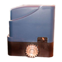
Install the tail rotor hub to the tail case. Use
M3*3 kimi screw to lock them and paste with
thread-locking fiuld.
Apply little amount lubricants for the tail
shaft evenly by sliding the tail rotor hub.
209.5370
11
0
109
108
107
071
037
116
115
114
113
111
071
049
1pcs
3pcs
037
2pcs
106
105
104
Trust Bearing
Tail Rotor Pitch Lever
Spacer
Hexagon Socket
Head Bolt
Step Washer
Pan Head Phillips Bolt
Tail Case, Right
Tail Rotor Shaft
Tail Rotor Shaft
Drive Pulley Cap
Tail Case, Left
Vertical Fin
Flange Head
Phillips Screw
ST3*20
M3*7.2
2.5* 5*2.5
M2.5*18
2.5* 4.8*4.5
4* 7*2.5
104
105
106
109
108
107
112
113
114
111
110
115
Pen Head Philips
Screw
ST3*10
Ball Linkage
Trust Bearing
4* 8*3
112
Tail Rotor Shaft
Drive Pulley
116
2pcs
1pcs
2pcs
1pcs
2pcs
2pcs
1pcs
1pcs
1pcs
1pcs
1pcs
1pcs
2pcs
076
076
Tail Drive Belt
1pcs
S2M 1028
M3*3
Kimi Screw
1pcs
032
032
078
078
Tail Boom
1pcs
14.8* 16*451
Apply amount of T43
thread-locking fiuld
Apply little amount lubricants
No
Description
Qty
need
Specification
No
Description
Qty
need
Specification