14
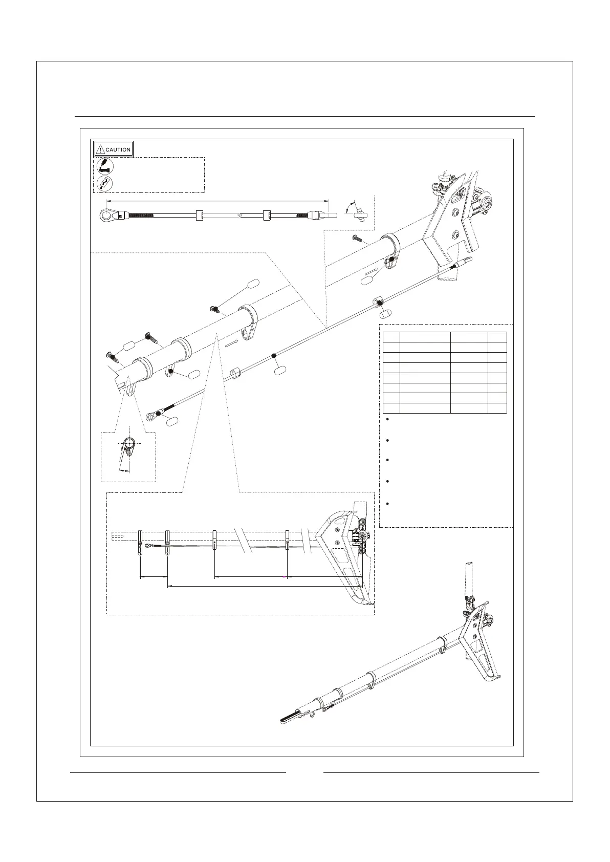
Install the ball link. Notice the ball links are
75 degree angle to each other and size
around 390mm.
Tail Pushrod
Install tail pushrod support, tail servo boom
screw to the tail boom. Notice the distance
of each parts as shown in diagram,
Install the pushrod slide into the tail pushrod
support with screws. Install the ball link to
the linkage ball of the tail rotor pitch lever.
SCALE 1:2
SCALE 1:2
Make sure that the tail servo boom mount
and tail boom are 15 degree angle to each
other.
The bottom right diagram shows the complete
installation.
2pcs
081
1pcs
080
2pcs
082
2pcs
019
2pcs
2pcs
037
079
079
082
084
037
080
081
019
Plastic Ball Link
Hexagon Socket
Head Screw
ST3*10
Tail Servo Boom
Mount
Tail Pushrod
M2.2*369
Pushrod Slide
Tail Pushrod Support
084
Hexagon Socket
Head Screw
ST2.6*8
2pcs
Complete Installation
150145
12.9
375
390
75
15
Apply amount of T43
thread-locking fiuld
Apply little amount lubricants
No
Description
Qty
need
Specification