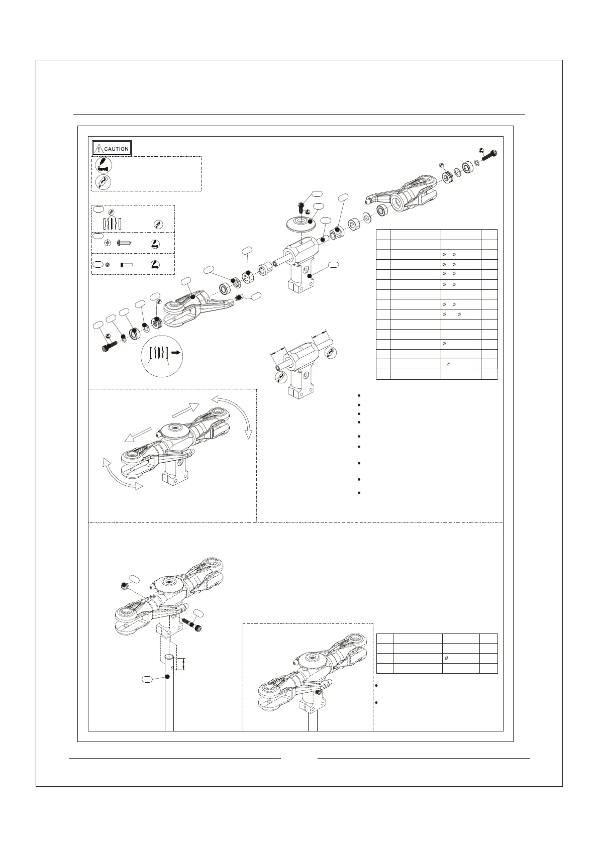
Rotor Housing Assemble Procedure
5
10.5
No
009
010
Description
Step Washer
Damper Ring
013
012
014
015
Hexagon Socket
Head Screw
Spindle
Fastener M3
Linkage Ball
Qty
need
2pcs
014
013
012
005
015
006
003
004
002
008
009
010
017
006
008
006
004
005
003
002
017
Six Socket Head Screw
Spacer
Trust Bearing
Washer
Bearing
5* 10*4.5
8* 11*0.5
5* 10*4
3* 7*0.8
M3*10
5* 9.5*1.5
4.5* 10*5
Blade Grips
5*67.5
2pcs
2pcs
4pcs
2pcs
2pcs
2pcs
2pcs
2pcs
1pcs
1pcs
M3*8
1pcs
S 4.75*L4
2pcs
012
002
Make sure the head of spindles
are same size and symmetric.
Complete isetup of rotor housing
Specification
M3*18Cap Screw
051
033
011
1pcs
1pcs
1pcs
M3
033
Main Shaft
8*156.5
Complete setup
diagram of rotor
housing
Install the spacer into the rotor housing properly.
Install the damper ring into the rotor housing properly.
The head of spindles must be same size.
Paste necessary amount of thread-locking fiuld
to the scew on centre hub cap.
Check the rotor housing after the installation. No
spare space is allow and choke when rotating.
Paste necessary amount of thread-locking fiuld
to the M3*10.
Paste little amount of lubricants bwhen installing
bearing. Notice the setup direction.
Setup the trust bearing inside the blade grips pr-
operly. Make sure the bearing rotate smoothly.
Setup the step washer in correct direction.
Plug the main shaft into the rotor housing.
(Into the correct position)
Screw must pass through the rotor housing
and main shaft and use M3 screw to fasten
them.
IN
OUT
AA
AA
051
011
Apply amount of T43
thread-locking fiuld
Apply little amount lubricants
Apply little amount
lubricants
No
Description
Qty
need
Specification
018
Rotor Housing
1pcs
Centre Hub Cap
018
Nylon Lock Nut