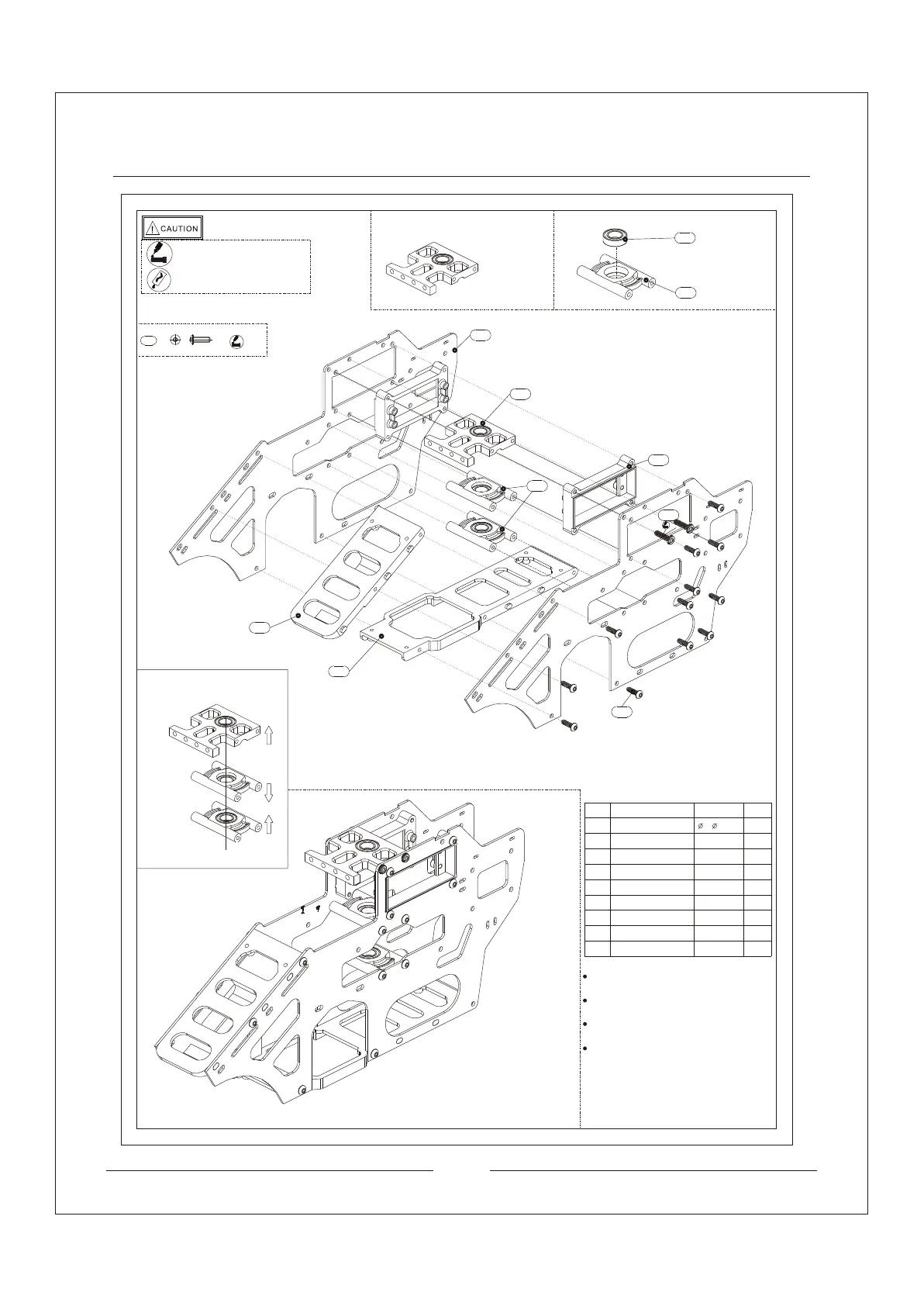
Frame Assemble Procedure
7
Install the main shaft hubs, bottom tray,
battery tray inside the main frame.
Install the main shaft retaining collars into
the plastic main shaft hubs.
Paste necessary amount of thread-locking
fiuld to the upper main shaft.
Make sure all the scews are locked and no
loose is allowed.
060
062
1pcs
048
043
040
041
039
037
24pcs
2pcs
2pcs
1pcs
2pcs
4pcs
1pcs
039
062
041
040
060
043
048
037
043
034
X2
Bearing installed correctly
Pen Head Philips Screw
ST3*10
Main Frame
Servo Hub
Upper Bearing Block Set
Lower Bearing Block Set
Bottom Tray
Battery Tray
034
3pcs
Main Shaft Retaining
Collar
8* 14*4
M3*10
Setup diagram of main shaft
048
Complete setup diagram
Apply amount of T43
thread-locking fiuld
Apply little amount lubricants
No
Description
Qty
need
Specification
Pan Head Screw