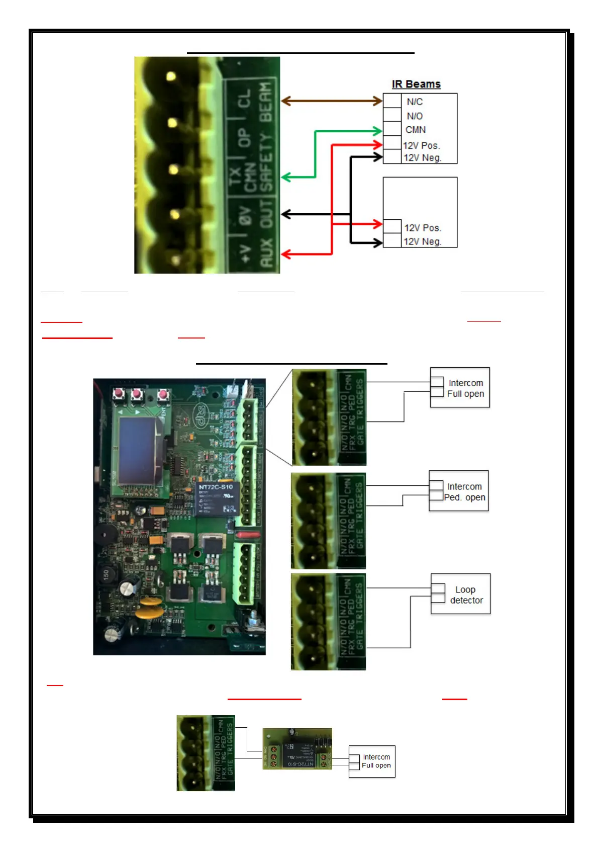
Diagram to connect IR Beams to PCB
Note: If SENTRY beams are fitted, then BEAM, CL on the PCB must be connected to N/O on the beam
(CL = N/C and OP = N/O)
Note: -
If no beams are connected, CL and TX CMN on the PCB by the Safety beams MUST be bridged.
Also NOTE- IR beams must be fitted if a DTS600 motor is installed.
Diagrams for gate open triggers
NB – When connecting intercoms to the control card, (TRG or PED) please ensure that your intercom
trigger output is potential free (ZERO voltage). If not, a gate relay module must be fitted.