EasyManua.ls Logo

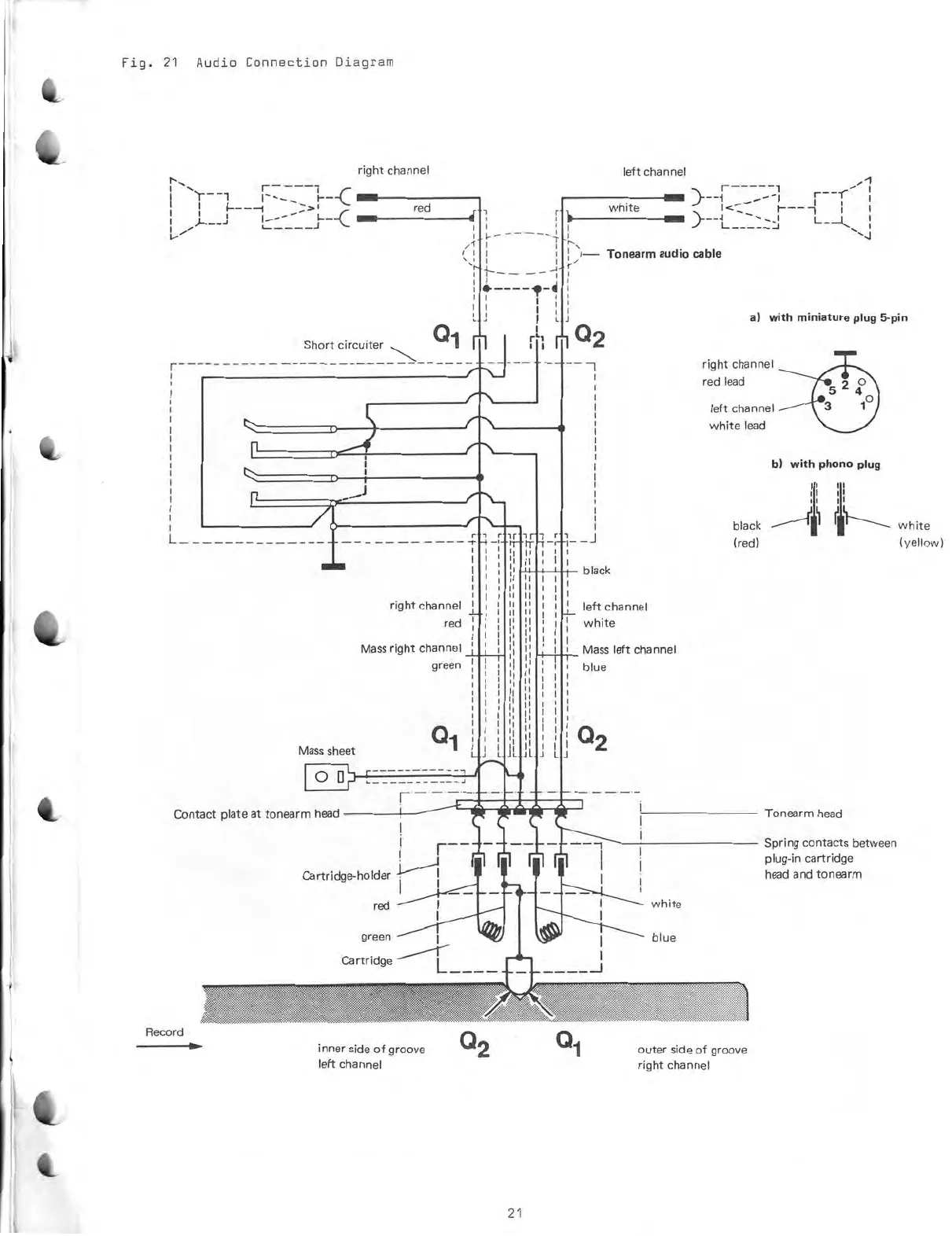
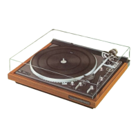
Dual 704 - Audio Connection Diagram

Dual 704
22 pages
Print Icon
To Next Page IconTo Next Page
To Previous Page IconTo Previous Page
Loading...
Fig.
21
Audio
Connection
Diagram
right
channel
r
_c
1
red
1---
--
Short
circuiter
0
1
n
r -
Mass
sheet
00
7"
-
•
7
—
•
-1
Nm
)----1
------1
.
,
___--
-
1
1
i
F
white
}
_
1
--
t
__
:22:i
L__
:
i
----
)
I
i
I
I
i
-I,-.
\,.
i
1
1)—
Tonearm
audio
cable
r
I-.
i
4
1
1>----e-1
1
i
1
1
1
i
i
I
L
i
i 0
2
r
1
left
channel
r r
-r
I I
I
right
channel
red
Mass
right
channel
green
0
1
1
r
1r
-
i
r
1
I
1_
left
channel
I
white
_J
bleck
Mass
left
channel
blue
0
2
a)
with
miniature
plug
5-pin
right
channel
red
lead
left
channel
white
lead
bleck
(red)
b)
with
phono
plug
I i
i i
U
I
Contact
plateat
tonearm
head
Tonearm
head
1
i
r
--
Record
Cartridge-holder
red
green
Cartridge
""
---"--r—
inner
side
of
groove
left
channel
Q
2
white
blue
outer
side
of
groove
right
channel
Spring
contacts
between
plug-in
cartridge
head
and
tonearm
white
(yellow)
21