Dann,legen
Sie eine 30 cm-Platte auf und
starten das Gerät. Wenn der
Abtaststift
jetzt
zu weit innen
auf der Schallplatte auf-
sefzt,
drehen
Sie die
Einstellschraube
ein
klein wenig nach links; wenn er zu weit
außen aufsetzt nach rechts.
Service
Alle Schmierstellen sind ausreichend
mit
Ol versorgt.
Damit wird unter
normalen
Betriebsbedingungen
lhr
Gerät
jahrölang
einwandf
rei f unktionieren.
Versuchen
Sie
an
keiner
Stelle selbsi
nachzuölen.
Es
müs.
sen Spezialöle verwendet werden. Sollte
lhr
Gerät
jemals
eine
Wartung
brauchen,
bringen
Sie es bitte entweder
zu lhrem
Fachhändler
oder
fragen
Sie
diesen nach
der Adresse der nächsten autorisierten
Dual-Kundendienstwerkstatt.
Bitte achten
Sie
darauf,
daß immer Original-Dual-ErsaE-
teile verwendet werden. Versenden
Sie
lhr
Gerät stets in der
Original-Verpackung.
Technische Daten
Phonochassis:
HiFi-Plattens,pieler
Dual
I21 5
Dear music lover
Please readt these instructions carefull)i
before
you
start using
your
Dual so that
you
will
not
encounter any
problems
resulting
from
faulty
connections or
handling.
Move
page
2 outward.
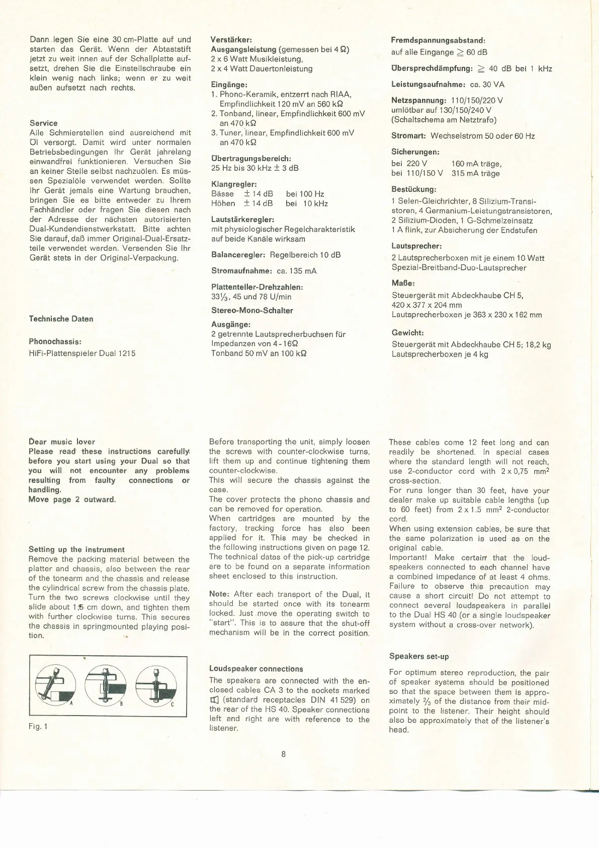
Setting up
the
instrument
Remove
the
packing
material
between the
platter
and
chassis, also
between
the
rear
of the
tonearm and the
chassis and release
the cylindrical
screw from
the chassis
plate.
Turn
the two
screws clockwise
until they
slide about 1S
cm
down, and tighten
them
with further
clockwise
turns. This
secures
the chassis
in
springmounted
playing
posi-
tion.
Verstärker;
Ausgangsleistung
(gemessen
bei
4 Q)
2 x 6
Watt Musikleistung,
2
x
4 Watt Dauertonleistung
Eingänge:
1. Phono-Keramik,
enfzerrt nach RIAA,
Empfindlichkeit
120 mV
an 560
kQ
2. Tonband, linear, Empfindlichkeit
600
mV
an
470
kQ
3. Tuner, linear, Empfindlichkeit
600 mV
an 470 kQ
Ubertragungsbereich:
25 Hz bis
30
kHz
+
3 dB
Klangregler:
Bässe
+
14
dB bei 100 Hz
Höhen
+
14
dB bei I0
kHz
Lautstärkeregler:
mit
physiologischer
Regelcharakteristik
auf
beide
Kanäle
wirksam
Balanceregler:
Regelbereich I0
dB
Stromaufnahme:
ca.
135
mA
Plattentel le
r- D re hzah le n :
331/3, 45 und 78
U/min
Stereo-Mono-Schalter
Ausgänge:
2
getrennte
Lautsprecherbuchsen
für
lmpedanzenvon4-16Q
Tonband 50 mV
an 100 kQ
Before trans,porting the unit, simply loosen
the screws with counter-clockwise turns,
lift them up
and continue tightening them
co unter-c lockwise.
This will
secure the chassis against
the
case.
The
cover
protects
the
phono
chassis
and
can be removed
for operation.
When
cartridges
are mounted
by the
factory,
tracking force
has also
been
applied
for it. This may
be checked
in
the following
instructions
given
on
page
12.
The technical
datas
of the
pick-up
cartridge
are to be
found on
a separate information
sheet enclosed
to this instruction.
Note: After
each
transport
of the Dual,
it
should
be started
once with its tonearm
locked.
Just.move
the
operating switch
to
"start".
This is
to assure
that the shut-off
mechanism
will
be in the
correct
position.
Loudspeaker
connections
The
speakers
are
connected with the
en-
closed
cables
CA 3 to the
sockets marked
{
(standard
receptacles
DIN 41
529)
on
the rear
of the
HS 40.
Speaker
connections
left
and right
are with
reference
to
the
listener.
Fremdspannungsabstand
:
auf alle Eingange
> 60 dB
Ubersprechdämpfung:
)
40 dB
bei
1
kHz
Leistungsaufnahme:
ca.
30VA
Netzspannung
1 1 1
0
|
1 50'l 22AV
umlötbar auf 1
30
1
1
5Ol 24O V
(Schaltschema
am Netztrafo)
Stromart: Wechselstrom
50 oder
60
Hz
Sicherungen:
bei 220V
160mAträge,
bei 1 1 0/1
50
V
31 5 mA
träge
Bestückung;
1
Selen-Gleichrichter,
I
Silizium-Transi-
storen, 4 Germanium-Leistungstransistoren,
2
Silizium-Dioden,
1 G-Schmelzeinsatz
1 A flink,
zur Absicherung
der Endstufen
Lautsprecher:
2 Lautsprecherboxen
mit
je
einem
'10
Watt
Spezial-Breitband-Duo-Lautsprecher
Maße:
Steuergerät mit
Abdeckhaube
CH 5,
42Ox377
x
204
mm
Lautsprecherboxen
je
363 x
230
x 1 62 mm
Gewicht:
Steuergerät mit Abdeckhaube
CH 5;
18,2
kg
Lautsprecherboxen
je
4 kg
These
cables come 12 feet long and
can
readlly be shortened. ln
special cases
where
the standard length will not reach,
use 2-conductor
cord with 2 x 0,75
mm2
cross-section.
For runs longer
than
30 feet,
have
your
dealer make
up suitable
cable
lengths
(up
to 60 feet) from
2 x 1.5 mm2 2-conductor
cord.
When
using extension
cables, be sure that
the
same
polarization
is
used as on the
original
cable.
lm.portantl
Make
certain
that the loud-
speakers
connected
to
each channel have
a combined
impedance
of at least 4
ohms.
Failure
to observe
this
precaution
may
cause
a short
circuit! Do not
attempt
to
connect
several
loudspeakers
in
parallel
to the Dual
HS 40
(or
a single loudspeaker
system without
a cross-over
network).
Speakers
set-up
For
optimum
stereo reproduction,
the
pair
of speaker
systems
should
be
positioned
so that
the
space
between
them is appro-
ximately
z/s
of
the distance
from
their
mid-
point
to
the listener.
Their height
should
also
be approximately
that
of the listener's
head.
@@@
Fig.
1
 Loading...