RFHU Operator’s Manual
32
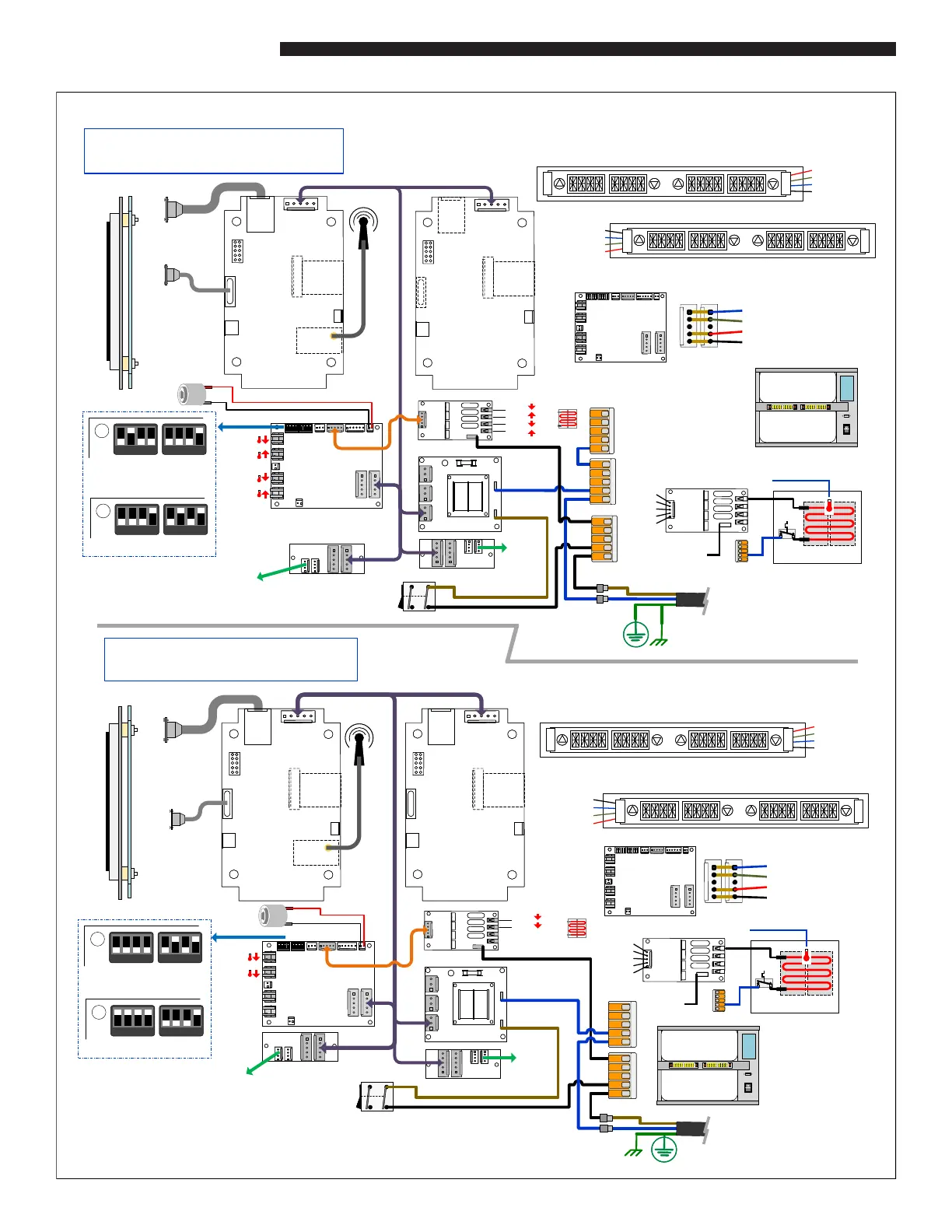
WIRE DIAGRAMS 2X2 TOP & BOTTOM HEAT
12 V P ower P CB12 V P ower P CB
12 V P ower P CB12 V P ower P CB
1 2 3 4 1 2 3 41 2 3 4 1 2 3 4
12Vdc
GND
CAN_H
CAN_L
D is pl ay
Flex Cable
(rear)
Speaker
8Ω 5W
DMX PCB
Rear Main Control
12Vdc
GND
CAN_H
CAN_L
D is pl ay
Flex Cable
(rear)
Speaker
8Ω 5W
DMX PCB
Rear Main Control
Rear
T im er
Bar
Line
Cord
Front
Power
Switch
DMX PCB Main Control
Touch S creen D isplay
DMX PCB Main Control
Touch S creen D isplay
Ethernet
12Vdc
GND
CAN_H
CAN_L
USB
D is pl ay
Flex Cable
(rear)
Speaker
8Ω 5W
DMX PCB
Front M ain Co ntrol
W iF i
Dau gh ter
Ethernet
12Vdc
GND
CAN_H
CAN_L
USB
D is pl ay
Flex Cable
(rear)
Speaker
8Ω 5W
DMX PCB
Front M ain Co ntrol
W iF i
Dau gh ter
Antenna
Rear
Ethernet
Front
USB
2 Wide Shelf (Top & Bottom Heat)
P1
P2
BLU (CAN_H)
W HT ( CAN _L)
RED ( 5V)
BLK (GN D)
P1 or P2
Con tr ol Po wer & CA N Bus
IO3 PCB
P1P2
IO3 PCB
P1P2
1 & 2
1 & 2
3 & 4
3 & 4
Front Timer Bar
2 Well E lem en t ( 30 0W)
12 0V = 48Ω / 2. 5A
20 8V = 14 4Ω / 1.4A
23 0V = 14 4Ω / 1.6A
24 0V = 14 4Ω / 1.7A
Temp Sens e R TD (1KΩ)
32 °F( 0°C) = 1, 00 0Ω, 18 0° F(8 2°C) = 1, 320Ω
Wire Diagram – RFHU 2x2
*Top & Bottom Heat
1
2
3
4
4
3
2
1
1
2
3
4
4
3
2
1
RED ( 5V)
W HT ( CAN _L)
BLU (CAN_H)
BLK (GN D)
Well 1 & 3 Well 2 & 4
Front Timer Bar
Well 1 & 2
Well 3 & 4
Well 1 & 2
Well 3 & 4
Beeper
1 2 3 4 1 2 3 41 2 3 4 1 2 3 4
Rear
Timer
Bar
Line
Cord
L1
Power
Switch
DMX PCB Main Control
Touch S cre en D isplay
DMX PCB Main Control
Touch S cre en D isplay
Ethernet
12Vdc
GND
CAN_H
CAN_L
USB
D is pl ay
Flex Cable
(rear)
Speaker
8Ω 5W
DMX PCB
Front M ain Co ntrol
W iF i
Dau gh ter
Ethernet
12Vdc
GND
CAN_H
CAN_L
USB
D is pl ay
Flex Cable
(rear)
Speaker
8Ω 5W
DMX PCB
Front M ain Co ntrol
W iF i
Dau gh ter
Antenna
Rear
Ethernet
Front
USB
High
Limit
L1
Temp Sen se
2 Wide Shelf
12Vdc
Hea t 1
Hea t 2
Hea t 3
Hea t 4
P1
P2
BLU (CAN_H)
W HT (CAN_L)
RED ( 5V)
BLK ( GN D)
P1 or P2
Con tr ol Po wer & CA N Bus
IO3 PCB
P1P2
IO3 PCB
P1P2
1 & 2
3 & 4
1 & 2
3 & 4
Front Timer Bar
22 1 -61 522 1 -61 5
2 Well E lem en t ( 30 0W)
12 0V = 48Ω / 2. 5A
20 8V = 14 4Ω / 1. 4A
23 0V = 14 4Ω / 1. 6A
24 0V = 14 4Ω / 1. 7A
Wire Diagram – RFHU 2x2
* Bottom Heat only
Well 1 & 2
Well 3 & 4
Well 1 & 2
Well 3 & 4
Beeper
High
Limit
L1
T emp S en se
12Vdc
Hea t 1
Hea t 2
Hea t 3
Hea t 4
22 1 -61 522 1 -61 5
ELC0541 Rev. D
1
2
3
4
4
3
2
1
1
2
3
4
4
3
2
1
BLK ( GN D)
BLU (CAN_H)
W HT ( CAN _L)
RED ( 5V)
Well 1 & 3Well 2 & 4
Rear Timer Bar
IO3 PCB
Ti me r Bar 5 V P CB
Timer Bar 5V P CB
Tr ia c PC B
1 2 3 4 1 2 3 4
1 & 2
1 & 2
3 & 4
3 & 4
1 2 3 4 1 2 3 4
Sw 1Sw 2
Sw 1Sw 2
20 8V , 2 30V , 2 40 V
Main Line Supply
120V Main Line Supply
S w1S w2
B otto m
Top
B otto m
Top
1
2
3
4
4
3
2
1
1
2
3
4
4
3
2
1
RED ( 5V)
W HT ( CAN_L)
BLU (CAN_H)
BLK ( GND)
Well 1 & 3 Well 2 & 4
Front Timer Bar
1
2
3
4
4
3
2
1
1
2
3
4
4
3
2
1
BLK ( GND)
BLU (CAN_H)
W HT ( CAN _L)
RED ( 5V)
Well 1 & 3Well 2 & 4
Rear Timer Bar
IO3 PCB
Timer Bar 5 V P CB
Ti me r Bar 5 V P CB
S w1S w2
B otto m
B otto m
1 2 3 4 1 2 3 4
1 2 3 4 1 2 3 4
Sw 1Sw 2
Sw 1Sw 2
20 8V , 2 30V , 2 40 V
Main Line Supply
120V Main Line Supply
22 1 -61 522 1 -61 5
22 1 -61 522 1 -61 5
22 1 -61 522 1 -61 5
L1
Ethernet
12Vdc
GND
CAN_H
CAN_L
USB
D is pl a y
Flex Cable
(rear)
Speaker
8Ω 5W
DMX PCB
Rear Main Control
Ethernet
12Vdc
GND
CAN_H
CAN_L
USB
D is pl a y
Flex Cable
(rear)
Speaker
8Ω 5W
DMX PCB
Rear Main Control
OPTIONAL
OPTIONAL
OPTIONAL
OPTIONAL
OPTIONAL
OPTIONAL
22 1 -61 522 1 -61 522 1 -61 522 1 -61 5
B otto m
Top
B otto m
Top
B otto m
B otto m
 Loading...