EasyManua.ls Logo

Dungs DMV Series - User Manual

Dungs DMV Series
2 pages
Print Icon
To Next Page IconTo Next Page
Loading...
1 … 2
MC • Karl Dungs, Inc. • DMV/6x2 Series Coil Replacement • Edition 2016.02 • P/N 261408
DMV/6x2 Series
Coil Replacement
Installation Instructions
Table of Contents
USA
CDN
Table of Contents ........................Page 1
Attention ................................Page 1
Procedure ...............................Page 2
1, 2, 3 ... = Action
= Instruction
Explanation of symbols
On completion of work on the
safety valve, perform a leakage
and function test.
Please read the instruction be-
fore installing or operating. Keep
the instruction in a safe place. You
nd the instruction also at www.
dungs.com If these instructions
are not heeded, the result may
be personal injury or damage to
property.
Any adjustment and application-
specic adjustment values must
be made in accordance with the
appliance-/boiler manufacturers
instructions.
Attention
Check the ratings in the speci-
cations to make sure that they
are suitable for your application.
[V] [A]
[Hz] [VA]
Safety
first
O.K.
The installation and maintenance
of this product must be done
under the supervision of an ex-
perienced and trained specialist.
Never perform work if gas pres-
sure or power is applied, or in
the presence of an open ame.
Question and Answer IconNeed help?

Do you have a question about the Dungs DMV Series and is the answer not in the manual?

Summary

Safety and Installation Attention Points

Qualified Personnel and Safety Precautions

Installation and maintenance must be done by trained specialists. Never work with gas pressure or power applied, or near an open flame.

Instruction Guidelines and Consequences

Read instructions before use and keep them safe. Failure to follow may cause injury or property damage.

Application-Specific Adjustments and Ratings

Adjustments must follow appliance/boiler manufacturer instructions. Verify application suitability with product ratings.

Coil Replacement Procedure

Preparation and Disassembly Steps

Disconnect power, close shut-off valve, remove electrical connector, and disassemble brake unit/knob and solenoid.

Coil Installation and Reassembly

Verify replacement coil, install it, replace washer, check/remount brake unit/knob, and secure screws.

Leakage and Function Testing

Perform external leakage test with gas pressure and power applied. Conduct a complete function test for valve operation.

Overview

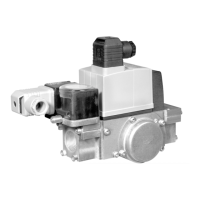
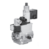
This document provides installation instructions for the DMV/6x2 Series Coil Replacement for Dungs Combustion Controls. It is a critical guide for ensuring the safe and proper maintenance of the device. The manual emphasizes the importance of qualified personnel for all installation and maintenance procedures, highlighting the potential for personal injury or property damage if instructions are not followed.

Function Description

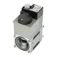
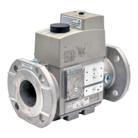
The DMV/6x2 Series Coil Replacement is designed to replace the solenoid coil on Dungs DMV/6x2 series valves, which are integral components in combustion control systems. These valves typically regulate gas flow, and the solenoid coil is responsible for their electrical actuation, allowing them to open and close as required by the control system. The replacement process involves disconnecting power, removing the old coil, and installing a new one, ensuring that the valve continues to function correctly and safely. The instructions also cover the inspection and testing of related components, such as the hydraulic brake unit or black adjustment knob, and the associated O-rings, to maintain the overall integrity and leak-tightness of the valve assembly. Proper coil replacement is essential for the reliable operation of the combustion system, preventing gas leaks and ensuring efficient fuel delivery.

Usage Features

The installation instructions are structured to guide users through a systematic replacement process. Key usage features include:

  • Safety First Approach: The manual prominently displays "Safety first O.K." and "Attention" sections, underscoring the critical need for safety precautions. Users are explicitly warned against performing work with gas pressure or power applied, or in the presence of an open flame. This highlights the inherent risks associated with working on gas-related equipment and the necessity of de-energizing the system before any intervention.
  • Step-by-Step Procedure: The "Procedure" section provides a detailed, numbered list of actions, starting from disconnecting power and closing the upstream manual shut-off valve, through the removal and installation of components, to final testing. This sequential approach ensures that users follow a logical progression, minimizing errors.
  • Visual Aids: Although not explicitly detailed in the provided text, the presence of figures (e.g., "Fig. 1") suggests that the full manual includes diagrams or illustrations to aid in identifying parts and understanding the steps, which is a crucial usage feature for technical instructions.
  • Component Identification: The instructions refer to specific parts like the "hydraulic brake unit," "black adjustment knob," "DIN electrical connector," and "solenoid," helping users to correctly identify and handle each component during the replacement process.
  • Verification Steps: Several steps involve verification, such as checking the replacement coil's electrical rating, inspecting O-rings, and performing leakage and function tests. These verification points are critical for confirming the successful completion of the replacement and the safe operation of the valve.
  • Troubleshooting Guidance: The manual advises users to contact Karl Dungs, Inc. for technical help or replacement if the valve does not operate properly after the procedure, indicating a built-in support mechanism for users encountering issues.
  • Language and Accessibility: The document is in English, with clear and concise language, making it accessible to a broad range of technical users. The inclusion of "USA" and "CDN" labels suggests that the product and instructions are tailored for North American markets.

Maintenance Features

The manual outlines several features that are crucial for effective maintenance of the DMV/6x2 series valves:

  • Qualified Personnel Requirement: A fundamental maintenance feature is the strict requirement that "The installation and maintenance of this product must be done under the supervision of an experienced and trained specialist." This ensures that only individuals with the necessary expertise and training perform the work, reducing the risk of improper installation or damage.
  • Pre-Installation Checks: Before installation, users are instructed to "Check the ratings in the specifications to make sure that they are suitable for your application." This proactive step prevents the installation of an incompatible coil, which could lead to malfunction or damage.
  • Leakage Testing: A critical maintenance step is the "external leakage test" performed after reassembly. Users are instructed to apply liquid leak detector around specific areas (gap between hydraulic brake unit/black adjustment knob, valve body, and solenoid) to identify any gas leaks. This test is vital for ensuring the safety and integrity of the gas system.
  • O-Ring Inspection and Cleaning: The instructions emphasize checking and cleaning O-rings, and replacing them if damaged. O-rings are crucial for maintaining a gas-tight seal, and their proper condition is essential for preventing leaks. This highlights a key preventive maintenance task.
  • Function Testing: A "complete function test" is required after the replacement, where power is applied to the valve to ensure both valves open and close properly. This confirms the operational integrity of the newly installed coil and the overall valve assembly.
  • Component Inspection: The bore in the cylinder shaft must be inspected for debris or burrs, and care must be taken to prevent dirt from entering the valve system. This attention to cleanliness and component condition is a fundamental aspect of good maintenance practice.
  • Adherence to Manufacturer Instructions: The manual stresses that "Any adjustment and application-specific adjustment values must be made in accordance with the appliance-/boiler manufacturers instructions." This ensures that the valve operates optimally within the context of the larger combustion system, maintaining efficiency and safety.
  • Documentation and Record-Keeping: The instruction to "Keep the instruction in a safe place" implies the importance of having readily available documentation for future maintenance or troubleshooting, which is a good maintenance practice.
  • Post-Maintenance Safety Checks: On completion of work on the safety valve, a "leakage and function test" must be performed. This final verification step ensures that the valve is safe and operational before returning the system to service.

Dungs DMV Series Specifications

General IconGeneral
Closing Time< 1 s
Opening Time< 1 s
ApplicationGas burner control
Max. Operating Pressure500 mbar
Valve ClassA
ApprovalsEN 161
Operating Temperature-20°C to +60°C

Related product manuals