Do you have a question about the Dungs MPA 5111 and is the answer not in the manual?
Details on rated voltage, frequency, fuse, protection, and environment.
Specifies output types, electrical data for MPA 5111 and extension modules.
Details input types, electrical data for MPA 5111 and extension modules.
Information on analogue inputs/outputs and integrated functions of extension modules.
Procedure to unlock the MPA, including limitations and extended unlocking.
Explanation of access levels and password entry for parameter modification.
Describes operation without and with valve check systems.
Parameters related to parameter stick, restart attempts, and flame status.
Parameters for LDW operating mode and its monitoring.
Parameters for temperature controller operation and customer ID settings.
Parameters for record ID and operating modes of PWM outputs.
Parameters for fan control, delay, ramp, and regulation.
Parameters for fan KP factor, TN factor, and pulse per rotation settings.
Parameters for fan allowed tolerance, minimum, and maximum speeds.
Parameters for selecting and configuring the stepped motor type.
Parameter defining the allowed tolerance for stepped motor operation.
Parameters for Valve Protection System (VPS) during startup and switch-off.
Parameters for controlling the activation and deactivation states of the additional valve.
Parameters for pre-aeration, ignition, safety time, and stabilization phases.
Parameters for standard mode duration and modulation degree settings.
Parameters for modulation degree step width and analogue value acceptance interval.
Parameters for regular switch-off transition time and power settings.
Parameters for defining restart attempts and duration in the waiting program.
Parameters that should not be changed by the user.
Procedure for loading parameter records from a stick and using continuous run function.
Using VisionBox and parameter sticks for programming curves and settings.
Definitions for burner capacity, modulation degree, curve point, and special point.
Specific errors originating from processor 2, including display issues.
List of basic system errors, their IDs, and potential causes.
Errors related to extended functions like fan, stepped motor, and modulation degree.
Application-specific errors, including parameter record issues and fan/motor faults.
Details on operational status, error, info, service, and parameterisation displays.
Visual guide to button functions and character displays on the MPA control panel.
Explanation of the operational status display showing individual process states.
How error messages are displayed and navigated using control keys.
How to access and view information like start counter and runtime meter.
Procedure to activate and use the service display for modulation percentage adjustment.
Guide to accessing and modifying parameters via the parameterisation display.
How to reset error memory, access levels, runtime, and start counters.
Procedure to view the last ten errors stored in the error memory.
Process for entering passwords when using parameter record sticks.
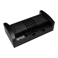
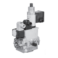
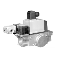
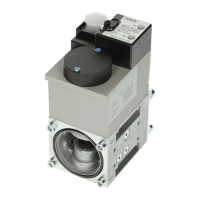
Visual identification of SAD 15, SAD 1.2 WG, SAD 3.0 WG, SAD 10 WG, SAD 1.5, SAD 3.0 (IP 40), SAD 1.2.
Illustration of rotation ranges for standard reference point of stepped motors.
Illustration of rotation ranges for exchanged reference point of stepped motors.
Table detailing mathematical angle positions for stepped motor reference points.
Detailed wiring diagram for the SAD15 stepped motor, including power and signal lines.
Table specifying power supply requirements for different stepped motor models.
| Brand | Dungs |
|---|---|
| Model | MPA 5111 |
| Category | Control Unit |
| Language | English |