Iftankis morethan20' fromtheboiler,a twostage
fuel unit shouldbe installedin place of the single
stagepump suppliedas standardequipmentwith
theburner.Makecertaintherotationandspeedare
the sameand the pump is suitablefor the burner
horsepowerrating.
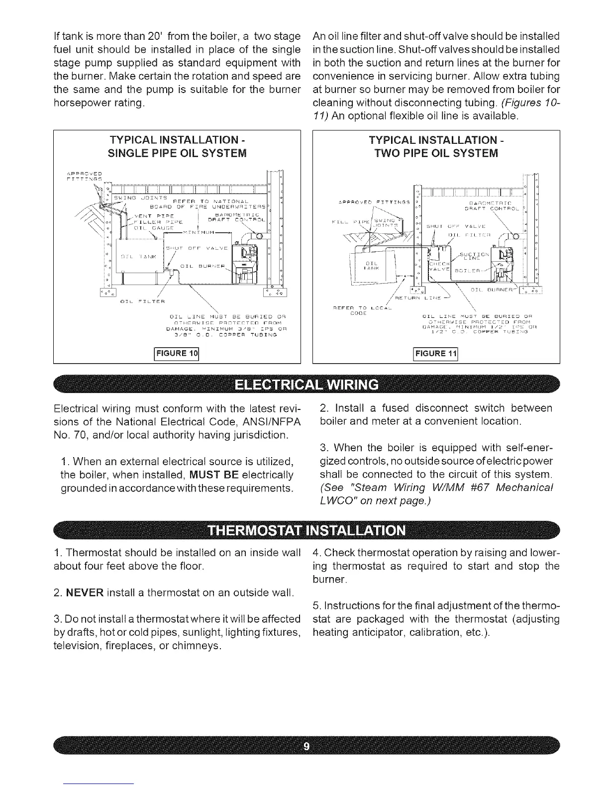
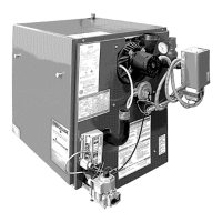
Anoillinefilterandshut-offvatveshouldbeinstalled
inthesuctionline.Shut-offvatvesshouldbeinstalled
inboththesuctionandreturnlinesattheburnerfor
convenienceinservicingburner.Allowextratubing
atburnersoburnermayberemovedfromboilerfor
cleaningwithoutdisconnectingtubing.(Figures 10-
11) An optional flexible oil line is available.
TYPICAL INSTALLATION -
SINGLE PIPE OIL SYSTEM
IFIGURE101
TYPICAL INSTALLATION -
TWO PIPE OIL SYSTEM
/
_EFER TO LOCAL
CODE
,\
\
[)AHA( [ "1 I Ni¢ltJbl I/'2
1/2 ' O _ COPPER TtJBZrJG
L''G°"E'll
Electrical wiring must conform with the latest revi-
sions of the National Electrical Code, ANSI/NFPA
No. 70, and/or local authority having jurisdiction.
1. When an external electrical source is utilized,
the boiler, when installed, MUST BE electrically
grounded in accordance with these requirements.
2. Install a fused disconnect switch between
boiler and meter at a convenient location.
3. When the boiler is equipped with self-ener-
gized controls, no outside sou rce of electric power
shall be connected to the circuit of this system.
(See "Steam Wiring W/MM #67 Mechanical
LWCO" on next page.)
1. Thermostat should be installed on an inside wall
about four feet above the floor.
2. NEVER install a thermostat on an outside watt.
3. Do not install a thermostat where itwill be affected
by drafts, hot or cold pipes, sunlight, lighting fixtures,
television, fireplaces, or chimneys.
4. Check thermostat operation by raising and lower-
ing thermostat as required to start and stop the
burner.
5. Instructions for the final adjustment of the thermo-
stat are packaged with the thermostat (adjusting
heating anticipator, calibration, etc.).