6
2.2 Installation conduit plan – power and communication circuits
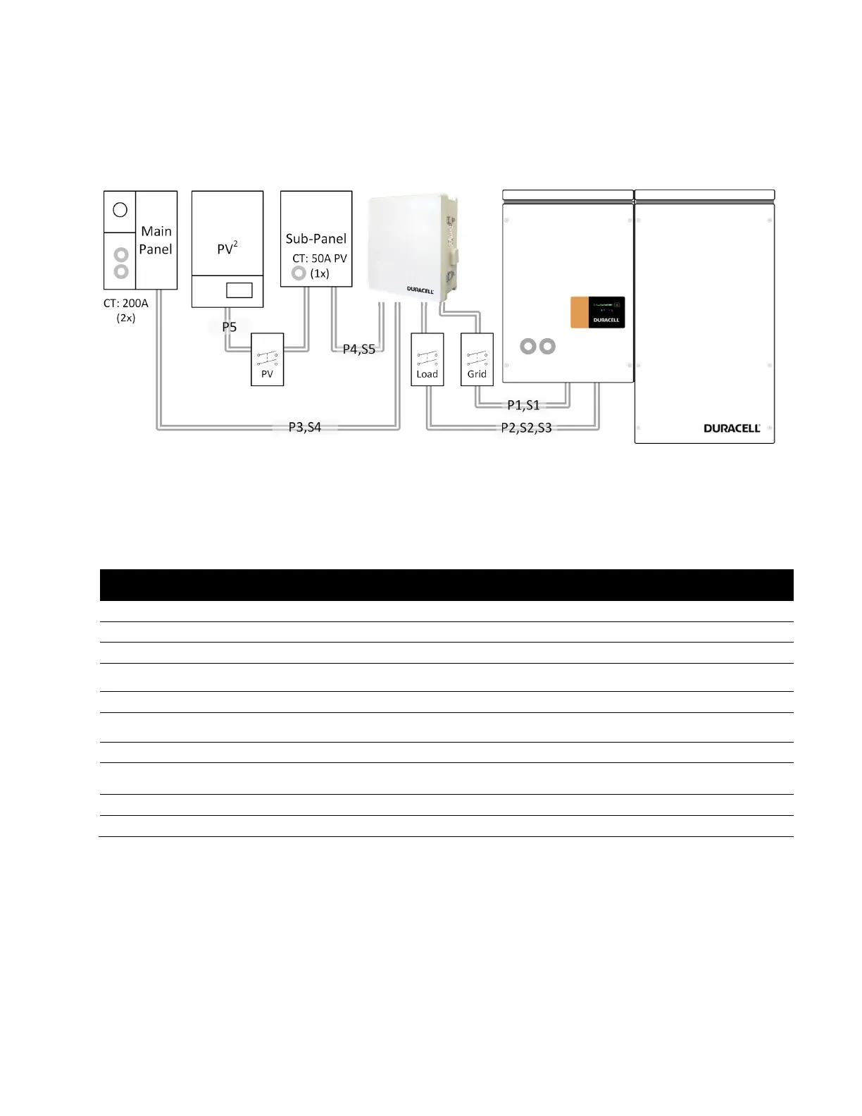
The following example outlines the conduit plan for power and communication circuits for a complete solar plus
storage system using the DURACELL HUB and the DURACELL POWER CENTER 5KW. (String PV inverter shown –
replace with equivalent AC combined micro-inverter output, where applicable).
Table 1: Circuit summary for a solar plus storage installation.
Ref
Circuit Definition
(recommended)
Circuit Protection
P1 ESS grid power 8/3 40 Amp
P2 ESS backup power 8/3 40 Amp
P3 Main panel power 8/3 40 Amp
P4 Backup panel 8/3
40 Amp feeder if total backup ccts exceed 40
Amp/240V rating
P5 Solar PV power 8/3 40 Amp
S1
3 meter patch cable included
CAT 5/6 STP -
S2 (x2) CT , 50 Amp 8 ft pigtail 18/2, 300V
-1
-
S3
AK1 Hub Control Signal cable
harness included , 10 ft
18/2, 300V -
S4 (x2) CT, 200 Amp 8ft pigtail 18/2, 300V
-1
-
S5 CT , 50 Amp 8 ft pigtail 18/2, 300V
-1
-
Note 1: Conductor type referenced where Hub is installed greater than 24” from the ESS. Signal wiring routed in
conduit with power must be 300V rated. For runs longer than 10 meters, signal separation from power is
recommended to minimize signal interference.
Disclaimer:
Manufacturer supplied components represented here are limited to the PCS/Battery, DURACELL HUB, and CTs for PV, battery, and
mains. All other materials and components represented are customer supplied. CEC/NEC electrical code compliance is the
responsibility of the designer and/or electrical permit holder. Source circuit disconnects for PV and ESS grid/load ports not shown.
Figure 9: Installation conduit plan for a solar plus storage installation (base model shown).


 To Next Page