12
5 Operation
The EMC inside the DURACELL HUB is commissioned using a web
browser. Refer to the DURACELL HUB Install & Commission Quick
Guide for complete instructions on setup for the DURACELL POWER
CENTER 5KW. The operation instructions within this manual are
limited to the power up and commissioning test sequence of the
DURACELL HUB only.
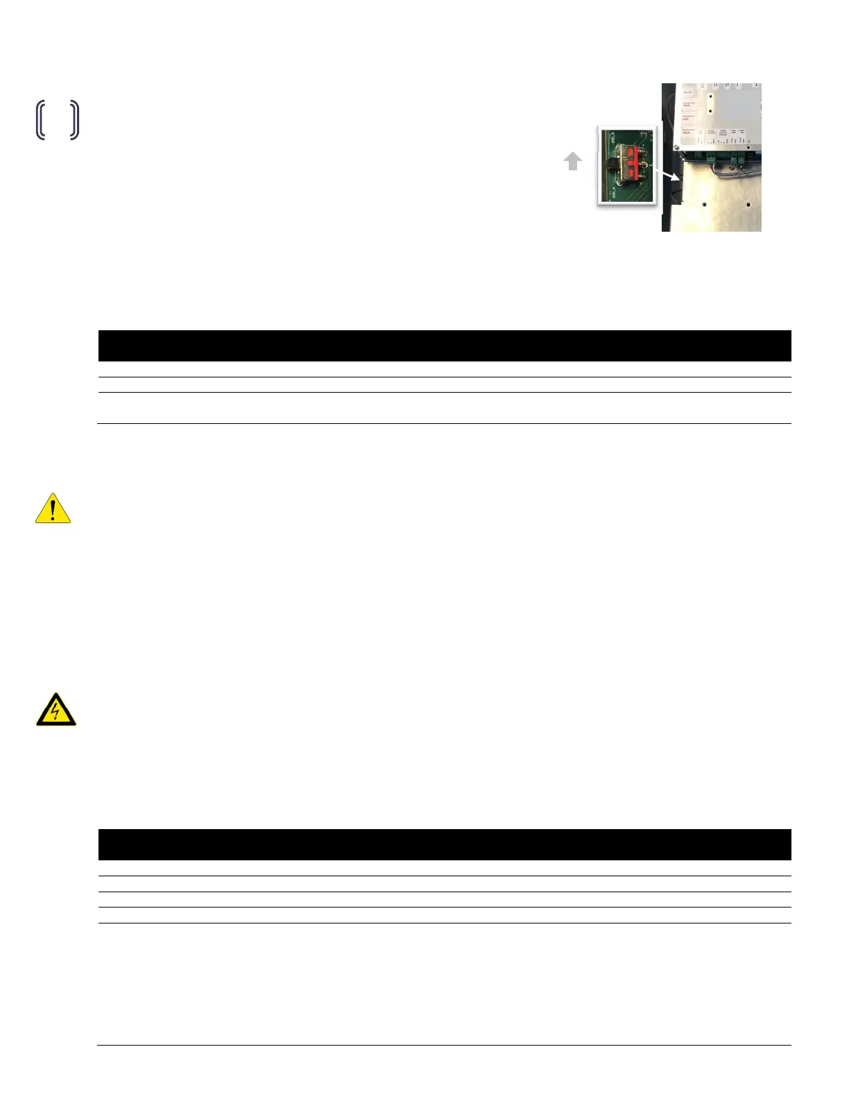
5.1 EMC selector switch
Confirm that the EMC selector switch is in the position [B].
5.2 Pre-startup checklist
The following is a recommended quality inspection checklist prior to power up of the system.
(√ )
AC power terminal clamps closed.
selector switch set to position
inspect and test ground continuity between the
DURACELL HUB and ESS.
5.3 Startup
IMPORTANT! The DURACELL HUB must be commissioned as part of the ESS. The startup procedure provided below
presumes that the PCS contained within the ESS is powered from the battery (DC source), and that the PCS is currently
displaying a valid SOC range and is operating in sleep/standby mode. Refer to the startup sequence of the DURACELL
POWER CENTER 5KW Installation & Startup Manual for instructions on startup (turning on DC source only). If AC
disconnects or the optional breaker kit has been installed between the PCS grid / load ports and the battery system,
leave them in the OFF position until the power up of the hub has been completed.
1. T
urn ON the DURACELL HUB breaker in the main panel.
Powering up the DURACELL HUB will supply power to the on-board EMC. The red and green lights on the bottom of
the EMC will flash for approximately 30 seconds, indicating initialization of the EMC. Following initialization, the
lights will remain solid.
CAUTION! Following initial power up of the ESS, shutting OFF the DURACELL HUB breaker at the main electrical panel
will automatically engage the ESS backup power source. The Hub will remain energized at the PCS Load and Load
ports while the ESS is in backup mode.
5.4 Post-startup checklist
The following is a recommended quality inspection checklist following power up of the system.
(√ )
EMC power up status: Green/Red LEDs flashing up to 30 seconds, then solid
Measure AC voltage at the
Measure AC voltage at the
Measure AC voltage at the load (backup panel connection) port. (L1
(start with AK1 relay connected).
1. Switch DURACELL HUB breaker at the main panel to the off position.
2. Switch the feeder breaker of the backup panel to the off position. Wait 4 seconds
for the ESS to transition the PCS into Offgrid mode.
3. Measure voltages (L1-N, L2-N) at the Load terminals of the Hub (~120VAC).
4. Pull the AK1 terminal (will switch the automatic bypass switch off)
5. Measure the voltages (L1-N, L2-N) at the Load terminals of the Hub (0 VAC).
6. Reconnect the AK1 terminal (after permission to operate (see sec. 5.5)
Figure 18
Figure 14
Figure 18
Figure 14
EMS
Figure 22: EMS selector switch.