16
Appendix B: Multi-mode transfer / bypass relay operation
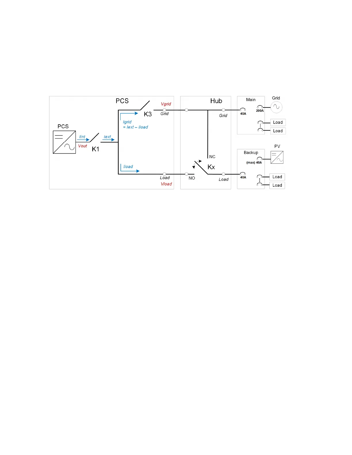
The DURACELL HUB and PCS within the DURACELL POWER CENTER 5KW provide fully automated multi-mode
operation, including utility interactive and backup (off-grid) operating modes. The diagram below highlights the
three main relay controls used to transfer the backup panel supply source and island the PCS to a micro-grid during
a grid outage. The battery portion of the DURACELL POWER CENTER 5KW is not shown.
Note: while the EMS is responsible for monitoring PCS states and controlling the battery discharge / charge rates,
the PCS is responsible for the relay controls, and thus does not rely on EMS communication for transfer of the
backup panel source.
F
igure 24: DURACELL HUB and PCS relay protection definitions in an AC coupled solar plus storage installations.
There are three main protection relays within the complete system, defined below, all of which have internal fail-
safe fault verification circuitry to prevent an unsynchronized PCS load to grid output connection.
Kx: DURACELL HUB bypass / transfer relay
The DURACELL HUB bypass / transfer relay ensures the backup panel is connected to the main panel with or without
an operating ESS. When standalone, the Kx relay bypasses the energy storage system to power the backup panel
from the main supply. It remains in the NC or bypass state until powered up with the ESS initialized and ready for
control. Once the energy storage system’s PCS is in a “ready” mode, the PCS will take over control of the backup
supply source by transferring Kx to NO, and closing K3 for an uninterrupted transfer. Kx will revert to an NC state
with or without a valid grid if the PCS reports a critical service state which prevents it from safely operating the K3
transfer relay.
Fail-safe: Critical failure of the Kx relay will prevent PCS operation and will result in loss of power to the backup
panel.
K3: PCS transfer relay
This relay operates with Kx as defined above when the ESS is in a “ready” state. See the table below for a complete
list of PCS states. This relay opens upon a grid outage to island the backup panel from the main panel. This relay
acts as the PCS grid timing / synchronization grid connect relay when the grid supply returns from an outage,
allowing seamless connection of the battery system and the backup panel circuits to the grid.
Fail-safe: Critical failure of the K3 relay will prevent operation of the PCS, but will allow the backup panel to be
supplied by the main panel via the DURACELL HUB.
 Loading...