11 Description of the service
program
Wear protective equipment to avoid any
risk of infection (e.g. liquid-tight protective
gloves, protective goggles, face mask).
The various unit functions can be checked with
the aid of the service program.
The individual program steps are:
– Display test
– Sediment level measurement
– Motor start and motor braking with rpm check
– Input and output signals
Function of the service key:
– By pressing the service key twice the next indi-
vidual program step is called up.
– By pressing the service key once that program
step is repeated.
A press of the service key is confirmed by an
audible signal.
11.1 Service program ON/OFF
On
– Press the service key and switch on the volt-
age supply to the unit.
– As soon as a signal melody can be heard,
release the service key.
The green, yellow and orange LEDs on the dis-
play panel light up (display test) and the serv-
ice program is activated.
Off
Switch off the main supply to the unit.
11.2 Display test
The display test is activated as soon as the serv-
ice program is started.
The LEDs on the display panel are checked. All
three LEDs must come on. There is also an audi-
ble signal, which can be switched off by pressing
the service button.
11.3 Sediment level measurement
While the service program is activated,
the safety check for the collector vessel is
deactivated.
The sediment level measurement can be used to
check the function of the sediment sensor and
the function of the LEDs.
Every time the service key is pressed, the sedi-
ment level is checked. If a test container is used,
the different 95% and 100% filling level on the
display panel can be revealed.
11.4 Motor start - motor braking
The drive motor starts up and is automatically
braked after the delay time. If the service key is
pressed before the end of the delay time, the
motor will immediately be braked.
This procedure can be repeated by pressing the
service key 1x again.
As a result of the rpm monitoring, the LED will go
from orange to green on start-up and from green
to orange during braking.
11.5 Input and output signals
– After activating the program point, the yellow
LED on the display panel flashes.
– A cycled DC voltage (c. 22-30 V) can be
measured on the rinsing unit connection (X1).
– Opening the collecting container causes the
orange display to illuminate on the display
panel.
– If a start signal is applied to socket X2 (lift out
the suction hose on the hose manifold) the
green LED illuminates on the display panel.
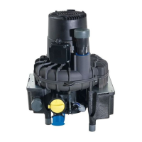
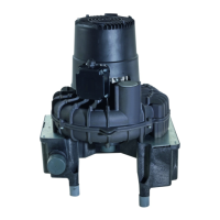
Assembly
28 9000-606-31/30 2101V005
EN
 Loading...