2.3
.0
. Assembling the enlarger
2.3.1. The baseboard
Place the baseboard
(30)
on the table with
the
rubber
feet downwards. Locate the
column
base (24) over the holes, with
the reinforcing ribs to the back.
Push the
bolt
(25) from above
through
the
washer (26) and the holes
of
the
column
base
a~d
the baseboard and secure it
with the wing nut
(27)
on top of
the
washer
(28)
.
The edge
of
the
column
base must be
parallel to the edge
of
the baseboard
to centre the
projected
image
correctly
in
the
middle
of the baseboard.
2.3.2. The column
Fit the
column
(16) from the
front
with
its threaded shaft
going
into the slot
of the column base. Place the washer (28)
over the threaded shaft and
screw
the
locking knob
(29)
in position. The column
can
now
be secured at the required
height with the knob
(29)
.
2.3.3. The enlarger head
Mount the
enlarger
head
(1)
on the
carrying arm
(19)
by screwing the
locking
knob (20) into the hole at the
rear of the
enlarger
head. The engage-
ment stop on the
enlarger
head must fit
into the groove on the carrying arm ;
l
a_;;~:!:~~~~;~
;:I,
then
the
locking
knob can be fully
.....
.......
tightened.
2
.3.4
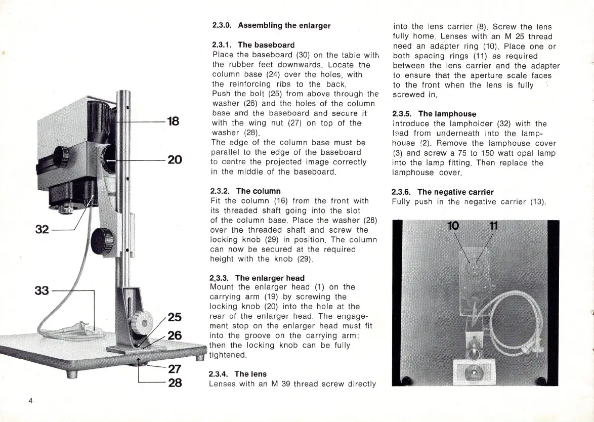
. The lens
Lenses with an M
39
thread
screw
directly
4
into the lens
carrier
(8).
Screw
the lens
fully home. Lenses with
an
M
25
thread
need
an
adapter
ri
ng (10) . Place one
or
bot
h spacing rings
(11)
as required
between the lens
carrier
and the adapter
to ensure that the aper
ture
scale faces
to the
front
when the lens is fully
screwed in.
2.3.5. The lamphouse
Introduce the lampholder
(32)
with the
I"':ad
from underneath into the lamp-
house (2). Remove the lamphouse cover
(3)
and
screw
a
75
to 150 watt opal lamp
into the lamp fitting. Then replace the
lamphouse
cover
.
2.3.6. The negative carrier
Fully push
in
the negative
carrier
(13).