Series MS2 Magnesense
®
II Differential Pressure Transmitter
Specications - Installation and Operating Instructions
Bulletin P-MS2
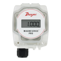
The Series MS2 Magnesense
®
II Differential Pressure Transmitter combines the
proven stable Piezo sensing technology of our original Series MS with additional
features to reduce installation time and simplify ordering. In this second generation
transmitter, we have added additional eld selectable pressure ranges so that each
model can have four selectable ranges along with four additional bidirectional ranges.
When using the pluggable integral display or the portable remote display tool, both
Metric and English engineering units can be selected via on board dip switches. Dual
current and voltage outputs allow users to simultaneously take either a current or
voltage output to their building controller and have a local test circuit for verication of
the output reading. The voltage output can be selected to be either 0 to 5 VDC or 0 to
10 VDC, while the current is always 4 to 20 mA. Both the current and voltage output
can also be inverted. Alternatively, the MS2 can be ordered with either a BACnet
or MODBUS
®
Communications protocol that will allow the transmitters to be daisy-
chained together.
Like the original Series MS, the second generation transmitter can be used as a linear
pressure output or a linear velocity output with the square root extraction done in
the transmitter. Additional parameters have been included to expand the square root
capability to include ow measurements.
BACnet
®
and Modbus
®
Communications protocol recommend limiting the number of
nodes in any segment to 32. Therefore, the transceiver may be rated at one unit load.
Fractional loads are also acceptable. The MS2 accounts as an eighth of a load on the
MSTP network.
SPECIFICATIONS
Supported Baud Rates: 9600, 19200, 38400, 57600, 76800, 115200.
Data Size: 8.
Parity: None.
Stop Bits: 1.
Service: Air and non-combustible, compatible gases.
Wetted Materials: Consult factory.
Accuracy: ±1% FS for 0.25˝ (50 Pa), 0.5˝ (100 Pa), 2˝ (500 Pa), 5˝ (1250 Pa), 10˝
(2 kPa), 15˝ (3 kPa), 25˝ (5 kPa); ±2% FS for 0.1˝ (25 Pa), 1˝ (250 Pa), ±0.1˝ (±25
Pa), ±1˝ (±250 Pa) and all bi-directional ranges.
Stability: ±1% / year FSO.
Temperature Limits: 0 to 150°F (-18 to 66°C).
Pressure Limits: 1 psi max., operation; 10 psi burst.
Power Requirements: 10 to 35 VDC (2 wire), 17 to 36 VDC or isolated 21.6 to 33
VAC (3 wire).
Output Signals: 4 to 20 mA (2-wire), 0 to 5 VDC, 0 to 10 VDC (3-wire).
Response Time: Averaging 0 to 240 sec, 2.5 Hz sample rate, 1.5 to 228 sec for
95% step change.
Zero & Span Adjustments: Digital push buttons.
Loop Resistance: Current output: 0 to 1250Ω max; Voltage output: Min. load
resistance 1kΩ.
Current Consumption: 40 mA max.
Display (optional): 5-digit LCD.
Electrical Connections: 3-wire removable European style terminal block for 16 to
26 AWG.
Electrical Entry: 1/2˝ NPS thread; Accessory (A-151): Cable gland for 5 to 10 mm
diameter cable.
Process Connection: 3/16˝ ID tubing (5 mm ID); Max. OD 9 mm.
Enclosure Rating: IP66.
Mounting Orientation: Diaphragm in vertical position.
Weight: 8.0 oz (230 g).
Agency Approvals: CE.
3-1/2
3-11/32
[84.84]
2-11/64
[55.12]
21/32
[16.51]
21/32
[16.51]
29/32
[23.02]
57/64
[22.60]
1/2
[12.76]
1-41/64
[41.71]
25/64
[9.97]
2-41/64
[67.24]
ø3-7/16
[ø87.31]
1/2 NPT
ø3-7/16
[ø87.31]
2-41/64
[67.16]
21/32
[16.55]
[16.55]
29/32
[23.02]
57/64
[22.67]
1/2
[12.77]
1/2 NPT
[3] 3/16 [4.76] HOLES
EQUALLY SPACED ON A
4.115 [104.52] B.C.
2-9/16
[65.12]
2-11/64
[55.25]
7-41/64[194.06]
15/64
[6.00]
Wall Mount Bracket
Duct Mount Bracket
DIN Mount Bracket
INSTALLATION
Surface Mount:
The transmitter should be mounted on a vertical surface with the connections directed
down to prevent moisture from entering either the pressure ports or the electrical cable
entry. The diaphragm must be vertical to minimize gravity effects on the diaphragm.
Attach the mounting ange to a at surface using three #8 x 1/2˝ pan head sheet metal
screws. Do not over tighten.
Duct Mount:
The transmitter should be mounted away from fans, corners, heating and cooling coils
and other equipment that will effect the measurement of the pressure.
1. To mount the transmitter, drill a .562˝ (12.70 mm) diameter hold into the duct.
2. Insert transmitter probe into the duct.
3. Mark location of three mounting holes on duct using mounting ange as template.
Drill holes.
4. Attach mounting ange to duct with three #8 x 1/2˝ pan head sheet metal screws.
Do not over tighten screws.
Electrical Connection:
The Series MS2 simultaneously transmits a 2-wire 4 to 20 mA current output and
a 3-wire 0 to 5 V / 0 to 10 V voltage output via a removable European-style three
conductor terminal block. The transmitter can be wired in one of the following three
ways to utilize the current and / or voltage output. The range of the voltage output can
be selected using the on board dip switches as described in the Dip Switch Settings
section of this manual.
Modbus
®
is a registered trademark of Schneider Automation, Inc.
DWYER INSTRUMENTS, INC.
P.O. BOX 373 • MICHIGAN CITY, INDIANA 46360, U.S.A.
Phone: 219/879-8000
Fax: 219/872-9057
www.dwyer-inst.com
e-mail: info@dwyermail.com