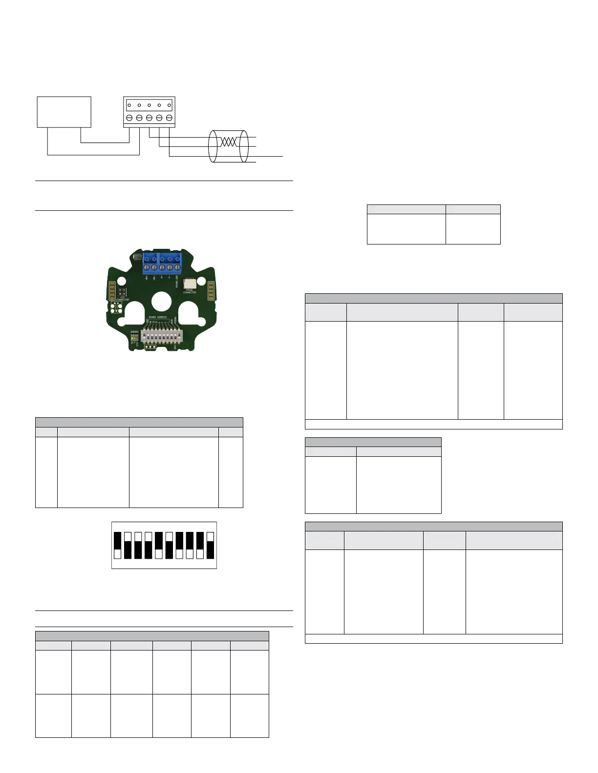
Wiring
Use maximum 18 AWG wire for wiring terminals. Refer to Figure 1 for wiring
information. Terminal blocks are removable for ease of wiring.
BACnet\Modbus
®
To make connections for a BACnet or Modbus
®
installation connect wiring as
shown in Figure 1.
Figure 1: RHPX digital wiring diagram
Note: Power and RS485 outputs are electrically isolated. The B(+) and A(-)
connections must be terminated at both ends with a 120 ohm resistor. If the
RHPX is an end device, it’s onboard 120 ohm resistor may be used. See DIP
switch settings to enable the termination resistor.
DIP switch settings
The RHPX has on board DIP switches to set the network address, type of network
(BACnet or Modbus
®
) and enablement of the 120 ohm termination resistor. Below
are the DIP switch settings denitions.
Communication Protocol Conguration
The following sections describe congurations that pertain to the BACnet and
Modbus
®
protocol.
Setting Protocol Address
Use the DIP switches to set the protocol address that the control system will
use to recognize the transmitter. Use the below table to identify how to set the
protocol address. The white rectangle indicates the switch position.
Default DIP switch setting: OFF-ON-ON-ON-ON-ON-ON-ON-ON-OFF unit
address 127, Modbus
®
, 120 Ω not connected
Note: Modbus
®
addresses must be between 001-247. BACnet addresses must be
between 000-127.
POWER
SUPPLY
-+
VDC+/VAC IN
VDC-/VAC RTN
B+
A-
RS485 GND
B+
A-
TO
DEVICE
RS485 GND
SUPPORTED BAUD RATES
Mode Baud Rates Data Size Parity Stop Bits
Modbus
®
RTU 9600
19200
38400
57600
76800
115200
8 Even
Odd
None
1, 2
BACnet MS/TP 9600
19200
38400
57600
76800
115200
8 None 1
DIP SWITCH SETTINGS
SW# On Off Value
1
2
3
4
5
6
7
8
9
10
ADDR BIT7=1
ADDR BIT6=1
ADDR BIT5=1
ADDR BIT4=1
ADDR BIT3=1
ADDR BIT2=1
ADDR BIT1=1
ADDR BIT0=1
MODBUS
120 Ω CONNECTED
ADDR BIT7=0
ADDR BIT6=0
ADDR BIT5=0
ADDR BIT4=0
ADDR BIT3=0
ADDR BIT2=0
ADDR BIT1=0
ADDR BIT0=0
BACNET
120 Ω NOT CONNECTED
128
64
32
16
8
4
2
1
INPUT REGISTERS
Register
Number
Description Data Type Range
0001-0002
0003-0004
0005-0006
0007-0008
0009-0010
0011-0012
0013-0014
0015-0016
0017-0018
0019-0020
8001-8016
8017-8020
8021-8028
8029-8032
Relative Humidity (%RH)
Dew Point (°F)
Dew Point(°C)
Enthalpy (BTU/lb)
Enthalpy (kJ/kg)
Absolute Humidity ( g/m
3
)
Absolute Humidity (lb/ million ft
3
)
Temperature (°F)
Temperature (°C)
Error Flags
Model Number
Serial Number
Firmware Version
Date Code
32bit oat
32bit oat
32bit oat
32bit oat
32bit oat
32bit oat
32bit oat
32bit oat
32bit oat
32bit integer
String(32)
String(8)
String(16)
String(8)
-
-
-
-
-
-
-
-
-
See Table Below
“RHPX-XXX”
“XXXXX”
“X.X.XR”
“XXXXXX”
Note: Register address is 1 less than register number
HOLDING REGISTERS
Register
Number
Description Data Type Range
0001-0002
0003-0004
0005
0006
0007-0023
Humidity Offset (%RH)
Temperature Offset (°F)
Humidity Display Unit
Temperature Display
Unit
Device Name
32bit oat
32bit oat
16bit
integer
16bit
integer
String(32)
-3.5 % to 3.5 % RH
-5.0 °F to 5.0 °F
0=Dew Point (°F)
1=Dew Point (°C)
2=Relative Humidity (%RH)
3=Enthalpy (BTU/lb)
4=Enthalpy (lb/ million ft
3
)
5=Absolute Humidity (kJ/kg)
6=Absolute Humidity (g/m
3
)
0 = °F, 1 = °C
“RHPX”
Note: Register address is 1 less than register number
ERROR FLAGS
Bit Possition Description
0
1
2
3
4
5
6
7
Invalid Address
Sensor Range Exceeded
Sensor Error
No Sensor
User Settings Invalid
Factory Settings Invalid
External Memory Failure
Internal Memory Failure
Intelligent Serial Conguration
The Intelligent Serial Conguration feature enables the device to determine the
baud rate, parity, and stop bits automatically from Modbus
®
or BACnet serial
trafc.
To perform Intelligent Serial Conguration:
1. Remove power from the transmitter.
2. Use the DIP switches to set a valid protocol address.
3. Reapply power.
The red LED will blink steadily when the transmitter begins monitoring for
serial trafc.
4. (Optional) If setting up a transmitter ofine or away from the main network,
you must send read requests to the unit manually.
The conguration process is complete after the device has successfully received
and processed a request. The red LED will also stop blinking. If a change to the
system requires an updated serial conguration, cycle power to the transmitter
to recongure.
Modbus
®
PROTOCOL REFERENCE
The following sections explain transmitter functions in systems employing
Modbus
®
communications protocol. The string data type is read as a stream.
Functions
The RHPX Comms supports the following Modbus
®
functions:
Function Name Function Code
Read holding registers
Read input registers
Write single register
Write multiple registers
03
04
06
16
Supported Modbus
®
communication protocol functions
The string data type is read as a stream of ASCII characters, with the rst
character sent in the MSB of the rst register, and the second character sent in
the LSB of the rst register and so on. If the string is shorter than the allotted size,
the remaining bytes are zero-padded.
123
45
6
7
8910
Example: Address 116 (64+32+16+4), BACnet, 120 Ω connected
 Loading...