Page 9 of 23
Remove C1 Replace C1 with a 0.33 µF film capacitor
(carries the number 334 on the body).
Remove C3.
Replace C3 with a 1000 µF electrolytic
capacitor. Slide a ½” piece of insulation stripped
from the supplied black 22 AWG wire over the
negative lead of C3. Stretch the negative lead
out as shown in Figure 3, leaving it full length
Install the positive lead of the new cap into the
hole formerly occupied by the negative lead of
the old C3.
Remove R2 Replace R2 by either a
1. 121 Ohm resistor, stock value, (brown,
red, brown, black, brown), or a
2. 243 Ohm resistor, gain lowering value,
(red, yellow, orange, black, brown),
depending upon how you answered the volume
control question at the beginning of the manual.
Connect only the lead that goes to Q1’s emitter,
leaving the other lead unconnected for now. See
Figure 3.
Cut a 2” long piece of white stranded 22 AWG
wire. Strip ¼” of insulation from each end.
Twist together the free ends of C3 and R2 with
one end of the white wire from the previous
step. Solder the connection.
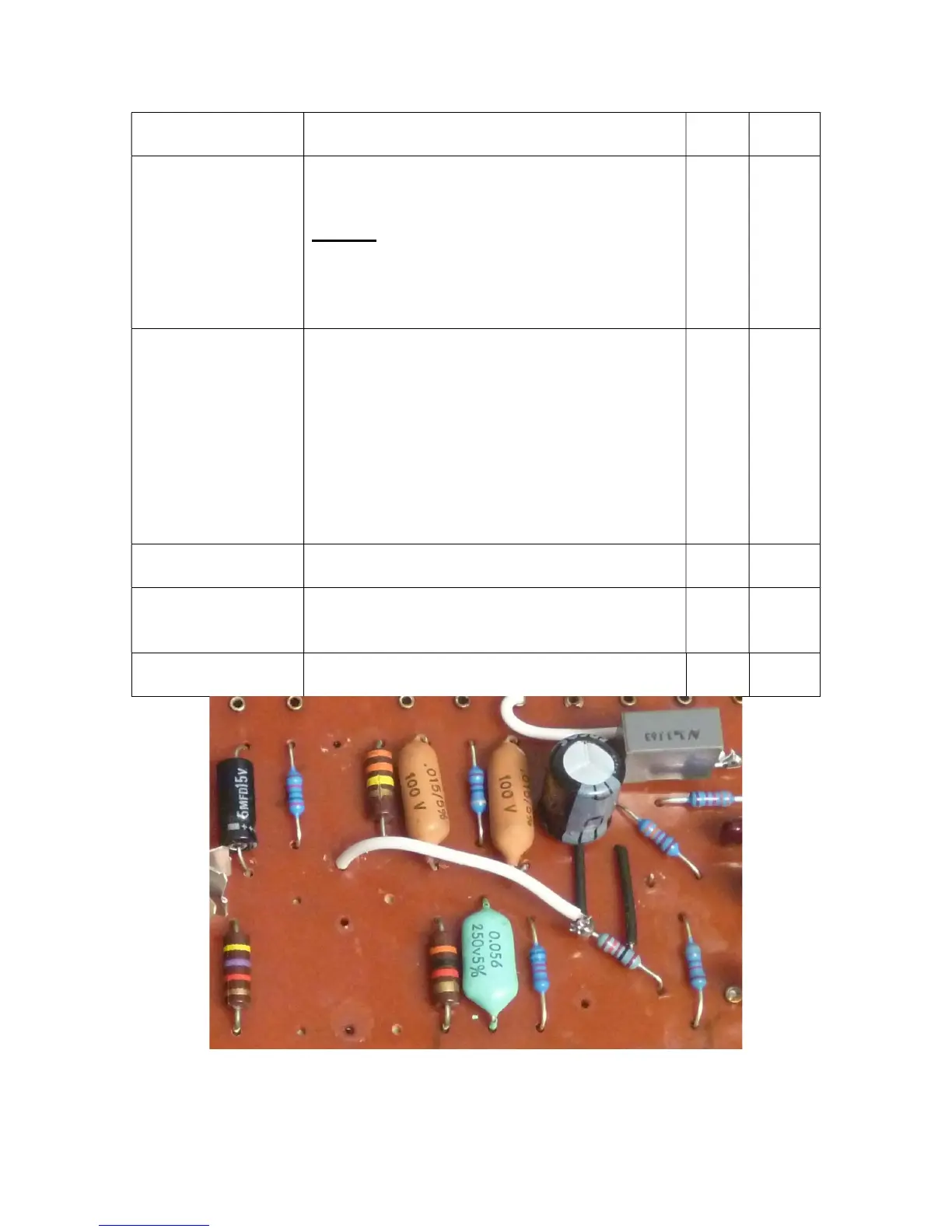
Connect the free end of the white wire to the
component hole on the PCB. See Figure 3.
Figure 3-Detail of R2-C3-white-wire connection