Page 10 of 15
Get masking tape and a pen so you can mark the wires that connect to C11 before
removing them. Mark them as indicated in this table.
Mark
Label
with
Number
of wires
Where wires connected Done()
3 terminal of C11, where the 4700 Ohms and 10 K
Ohm resistors come together.
1 terminal of C11, the other side of the 10 K resistor
1 terminal of C11, the other side of the 4700 Ohm
resistor
4G 4 Can of C11, terminal where 4 wires come together
2G 2 Can of C11, terminal where 2 wires come together
5. Remove the two screws, nuts, and lock washers that hold C11’s clamp into the
chassis. Remove C11 along with the two resistors.
6. Save the capacitor clamp, but neither the capacitor the resistors will be re-used.
Install the New Power Supply
7. Attach the mounting brackets to the assembled power supply PCB using two 6-
32x1/4” sems screws (sems screws have the captive lock washer). Make sure that
they’re both straight and tight.
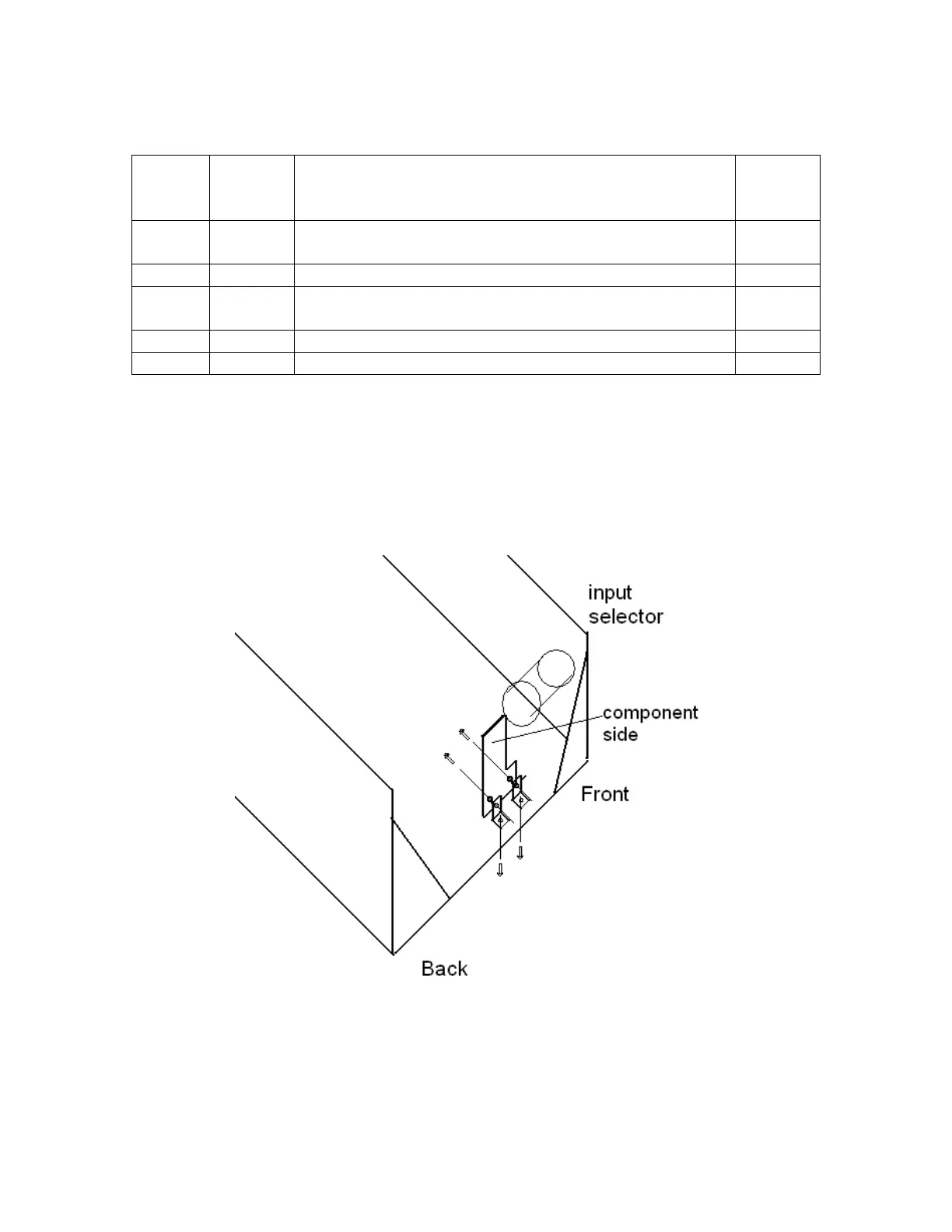
Figure 6-Mounting the power supply to the SCA80
8. Use the old mounting holes from C11 to fasten the brackets to the chassis. See
Figure 6.