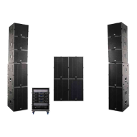
10. SYSTEM AMP RACKS
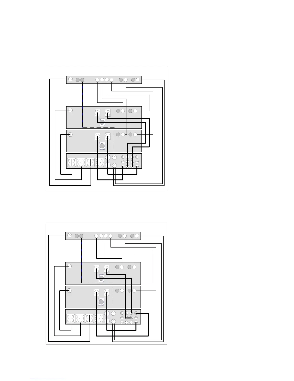
The two illustrations show the internal cabling of the COBRA SYSTEM RACK from the rear. The control of
the active 2-way COBRA and active 4-way COBRA-4 SYSTEMS is effected by their respective system
racks (CSR-12 in the case of the COBRA SYSTEM and CSR-4 in the case of the COBRA-4 SYSTEM) which
come pre-wired and factory-programmed.
In the CSR-12, the DSP 244 controlle
operates in stereo 2-way mode and
provides the integrated L 2400 powe
amplifiers with sub and mid/high
signals.
The output signals of the L 2400 powe
amplifiers (TOP above and SUB below)
are connected internally to the 4-pin
system sockets at the CP-44 fron
panel (Sub signals on 1+/1- and
mid/high signals on 2+/2-).
Mains power is provided by the 16
CEE plug on the front panel and the 4
Schuko sockets at the rear (L1 – sub-
amp, L2 – mid/high amp and controller,
L3 – free).
The XLR In/Out sockets on the front fo
RS-485 control are connected
internally to the DSP 244 and afte
conversion of the controller allow the
rack to be controlled remotely from a
PC using CrossMax editor software.
In the CSR-4, the controller operates in
mono 4-way mode and provides the
lower L 2400 with a sub signal on
Channel A and a low signal on
Channel B. The upper L 2400 is
provided with mid signals on Channel
A and high signals on Channel B.
The outputs of the power amplifiers are
connected to the 4- and 8-pin system
sockets of Channel A on the fron
panel. The complete LF control of the
rack is also effected via Channel A.
The Sub signal is available on the 4-pin
system sockets on pins 1+/1-. The
remaining signals are on the 8-pin
system sockets (Low – 2+/2-, Mid
3+/3- and High – 4+/4-) and drive the
stacked or flown TOP and FAR
cabinets via a single cable.
RS-485 and AC connectors are also
available as described for the CSR-12.
A
B
L-1 L-2 L-2 L-3
RED
YELLOW
4 3 2 1
IN 1IN 2
4
2
3
1
4/1
4/2
4/1
4/2
RS 485
OUT IN
B
B
A
A
INPUT
B
A
GREEN
Channel B
Channel A
Channel B Channel A
COBRA SYSTEM RACK CSR-12
A
B
L-1 L-2 L-2 L-3
RED
YELLOW
4 3 2 1
IN 1IN 2
4
3
2
1
4/1
8/2
RS 485
OUT IN
B
B
A
A
INPUT
B
A
GREEN
Channel B
Channel A
Channel B Channel A
8/48/3
COBRA-4 SYSTEM RACK CSR-4
 Loading...