Do you have a question about the Dynacord PSX 1250 and is the answer not in the manual?
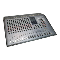
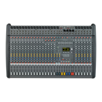
This document is a user manual for the Dynacord PSX 1250, a 12/16 channel power mixer. It provides detailed information on the device's functions, technical specifications, usage, and important notes for operation and maintenance.
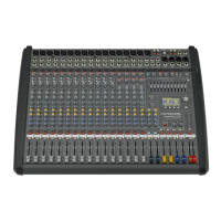
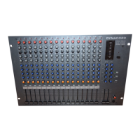
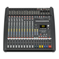
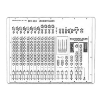
The Dynacord PSX 1250 is a compact power mixer equipped with a wide range of features designed for versatile audio mixing and amplification. It offers 12 input channels, consisting of 8 Mic/Line and 4 Mic/Line Stereo channels, allowing for the connection of various program sources such as keyboards, drum machines, tape recorders, and additional mixing desks. The stereo input channels can also function as regular mic input channels. All mic inputs are electronically balanced and feature XLR sockets, with 48V Phantom Power switchable for condenser microphones.
The mixer incorporates two separate digital 16-bit stereo effect units. One unit provides 6 reverb and 8 delay programs, along with 2 special effects, including different natural-sounding stereo reverb programs, special stereo programs combining reverb with additional echoes, and a stereo chorus program optimized for vocals, brass, and woodwinds. The ARS 10 DSP effects board offers 8 different delay and echo programs with front-panel controllable echo repeats. The second digital effect unit generates 16 different delay, flanging, chorus, and doubling programs.
The master section is comprehensive, featuring separate control functions for tape playback and record, connections for an additional external stereo effect unit, separately controllable AUX/LINE output/input, and a large 3-way LED level meter for the power amplifiers.
The PSX 1250 utilizes PCA processor power amplifiers designed with advanced Hi-Power MOS technology. These amplifiers linearize the frequency and phase response of connected loudspeaker cabinets in the low-frequency region using a 2nd-order shelving EQ, with corner frequencies matched to modern high-efficiency loudspeaker cabinets. A built-in fast-acting limiter prevents excessive overdrive. The power outputs are equipped with Speakon adapters, ensuring safe and loss-free connections for loudspeaker cables with large cross-sectional areas.
Caution: The unit must be protected from humidity to prevent the risk of fire or electric shock.
1. Mic Input: Electronically balanced XLR inputs for low-impedance microphones. Phantom-powered microphones can be connected. 2. Line Input: Unbalanced inputs for instruments and other high-level signal sources. Inserting a plug into this socket switches off the XLR input. 3. Gain + Peak LED: Controls input sensitivity (-56 dBV to -20 dBV). Adjust so the PEAK LED lights up only briefly at peak levels for optimal S/N ratio. A continuously lit PEAK LED indicates 10 dB headroom before audible distortion. EQ adjustments influence signal level, so recheck GAIN after EQ. 4. Equalizing: A 4-band equalizer (HI, HI-MID, LO-MID, LO) provides comprehensive control over frequency regions. Turning controls right increases, left decreases. Start from a neutral position. Avoid extreme settings; small corrections usually suffice. Gentle operation of mid controls can prevent acoustic feedback.
EQ Specifications:
5. Effect 1: Post-fader control for adjusting the EFFECT 1 level. Signal level depends on the channel fader (9). Control send signal carefully; PEAK indication on the effect module should only light briefly at dynamic peaks. Continuous lighting indicates overdrive. This path can drive an external effect unit or a separate monitor power amp. 6. Effect 2: Post-fader control for sending a signal to the built-in digital effect unit (reverb/echo). Signal level depends on the channel fader (9). Control send signal carefully; PEAK indication on the effect module (49) should only light briefly at dynamic peaks. Continuous lighting indicates overdrive. 7. Monitor: Controls the monitor power amp, independent of the channel fader (9). 8. Pan: Determines the stereo position of the input signal. In the central position, the signal is equally divided between left and right master channels. 9. Channel Fader: Adjusts the volume of the single channel and balances between individual channels. Aim for the 0 dB position for sufficient control displacement. Master volume is controlled by master faders.
10. Mic Input: XLR inputs for low-impedance microphones. Phantom-powered microphones can be connected. 11. Line L/Mono + R Input: Stereo input channels for various stereo signal sources (drums, synthesizers, samplers, submixers). Can also be operated in mono. XLR for low impedance mics, Jack LINE L/MONO for higher level sources. 12. Gain + Peak LED: Controls input sensitivity (-56 dBV to -20 dBu). Adjust so the PEAK LED lights up only briefly at peak levels for optimal S/N ratio. Continuous lighting indicates 10 dB headroom before audible distortion. EQ adjustments influence signal level, so recheck GAIN after EQ. 13. Equalizing: A 4-band equalizer (HI, HI-MID, LO-MID, LO) provides comprehensive control over frequency regions. Turning controls right increases, left decreases. Start from a neutral position. Avoid extreme settings; small corrections usually suffice. Gentle operation of mid controls can prevent acoustic feedback.
EQ Specifications:
14. Effect 1: Post-fader control for adjusting the EFFECT 1 level. Signal level depends on the channel fader (18). Control send signal carefully; PEAK indication on the effect module (41) should only light briefly at dynamic peaks. Continuous lighting indicates overdrive. This path can drive an external effect unit or a separate monitor power amp. 15. Effect 2: Post-fader control for sending a signal to the built-in digital effect unit (reverb/delay). Signal level depends on the channel fader (18). Control send signal carefully; PEAK indication on the effect module (56) should only light briefly at dynamic peaks. Continuous lighting indicates overdrive. 16. Monitor: Controls the monitor power amp, independent of the channel fader (18). 17. Bal: Determines the stereo position of the input signal. In the central position, the stereo signal is equally divided between left and right master channels. 18. Channel Fader: Adjusts the volume of the single channel and balances between individual channels. Aim for the 0 dB position for sufficient control displacement. Master volume is controlled by master faders.
19. Master RET/SEND: Jacks for looping an equalizer or other external processors into the master signal path. RETurn jacks interrupt the master signal. SEND jacks can be used as master output for additional power amps. 20. Left + Right / Monitor LED Level Meter: Shows power modulation of the power amplifiers. +3 dB to +6 dB indicates risk of overdriving. Avoid overdriving to prevent damage to the unit or loudspeakers. * TBC (Thermal Brain Circuit): The PCA power amps have high short-term peak output power (dynamic headroom of 1.5 dB, equivalent to 350 Watts/4 Ohms). The TBC circuit simulates a woofer's thermal behavior, reducing power output to rated (250 W/4 Ohms) during continuous overdriving or square wave modulation to protect the loudspeaker system. Note: TBC may not completely protect speakers with less power capability. * BUSY LED: Lights up when the limiter is activated. Continuous lighting indicates danger of overdriving; reduce output volume. * PROCESSOR ON LEDs: Indicate the unit is ready for operation. 21. Standby + LED: Mutes MASTER L+R and MONITOR outputs when pressed. The red LED blinks, indicating the unit is muted (e.g., during breaks). 22. Master L + R: Master volume control for the left and right master outputs. * Speaker Outputs: Professional Speakon connectors ensure safe and loss-free connections for high-powered loudspeaker cables (up to 4 x 2.5 mm²).
23. Tape Playback: RCA sockets for tape or cassette playback. Volume is controlled by the TAPE RET control (27) and is independent of master faders (22). 24. Tape Send: RCA sockets for master bus signal recording. Recording level is controlled by the TAPE SEND control (25) and is independent of master faders (22). 25. Tape Send Control: Stereo control knob for adjusting the output signal to the TAPE SEND sockets (24), driving a connected tape recorder or cassette player. 26. Tape to Mon: Adds the tape signal to the MONITOR section. Volume is independent of RET controls (27). Useful for playback performances. 27. Tape RET Control: Stereo controls adjust tape playback volume. This signal feeds in behind the Master L+R faders (22) and is independent of their position. Allows playing tape signals at any volume without altering master volume.
28. Monitor Break RET/SEND: Jacks for looping an equalizer or other external processors into the monitor signal path. RET jack interrupts the bus signal. SEND jack can be used as an output for additional monitor power amps. 29. Equalizing: A 3-band equalizer (HI, MID, LO) provides comprehensive control over frequency regions for the monitor signal. Turning controls right increases, left decreases. Start from a neutral position. Avoid extreme settings; small corrections usually suffice. Gentle operation of mid controls can prevent acoustic feedback. 30. Monitor: Volume control for the monitor bus output and monitor power amplifier.
31. Line In L/Mono + R: Jacks for feeding in a stereo signal (e.g., from submixers). Level depends on the position of the master faders. 32. Line Out L + R: Jacks for taking the master bus signal (pre-master fader). The LINE OUT signal is independent of the MASTER L+R faders (25). Can be used to feed a separately controllable master bus signal to a master mixing desk or a separate amplifier/speaker circuit for monitor purposes. 33. Line to Mon: Adds the LINE signal to the MONITOR section. Volume is independent of the LINE master fader (35). 34. Line Out Control: Stereo control knob for adjusting the output signal for the LINE OUT jacks (31). 35. Line In Control: Stereo control knob for controlling the LINE IN signal from the LINE IN sockets (35) and mixing it into the master bus. Master volume depends on the MASTER L+R faders (22).
36. Extern Effect/RET: Jacks for looping in external effect units into the EFF 1 path, parallel to the built-in EFF 1. Use RET L/MONO for mono units. RETURN sockets connect to the output of the external effect unit. 37. Extern Effect/SEND: EFFECT SEND jack connects to the input of the external effect unit. 38. Program Select: Program switch for 16 stereo effect programs of the built-in effect 1 unit. * Reverb Programs: Small, Medium, Large Reverb, E/R Small, E/R Medium, E/R Large, Chorus, Pitch. * Delay Programs: D1-D8 (60 ms to 460 ms), L-R DLY (170 ms to 460 ms). 39. Repeat + LED: Adjusts the amount of echo repeats for delay programs. Green LED indicates activity. 40. EFF 1 to Mon: Mixes the reverb or echo signal from EFF 1 into the monitor channel. 41. EFF 1 Send + Peak LED: Adjusts input level for the built-in effect unit and output level on EXTERN EFFECT SEND jack (37). PEAK LED indicates risk of overdriving; adjust so it lights briefly at dynamic peaks. 42. Bal: Determines the stereo position of the effect signal. Central position divides signal equally between master channels. Turning left attenuates the right channel, turning right attenuates the left. 43. EFF 1 On/Off + LED: Pushes button (green LED lights up) switches on the built-in effect module. Does not affect external effect units. For foot switch control, EFF 1 must be on via this button. LED changes with foot switch status. 44. EFF 1 RET: Stereo fader for mixing the effect 1 signal and/or external effect signal to the master signal.
45. Program: Program switch for 16 stereo effect programs (echo effect) of the built-in effect 2 unit. * Stereo-Delay Programs: 1-10 (100 ms to 512 ms). * Stereo-Effects Programs: 11-12 Guitar Flanger, 13-14 Guitar Chorus, 15-16 Voice Doubling. 46. Intens + LED: Adjusts effect volume for delay or effect programs. Green LED indicates activity. 47. Repeat + LED: Adjusts amount of echo repeats for delay programs and feedback for flanger effects. Green LED indicates activity. 48. EFF 2 to Mon: Mixes the effect signal from EFF 2 into the monitor channel. 49. EFF Send + Peak LED: Sets input level for the built-in effect unit. PEAK LED indicates risk of overdriving; adjust so it lights briefly at dynamic peaks. 50. Bal: Determines the stereo position of the effect signal. Central position divides signal equally between master channels. 51. EFF 2 On/Off + LED: Pushes button (green LED lights up) switches on the effect module. 52. Effect On/Off FS-11: Both effect units can be switched on/off by an optional foot switch FS-11. Both effects must be on, and FS-11 connected. Red LED on foot switch lights up if effect is ON. EFF ON/OFF LEDs show foot switch status. 53. EFF 2 RET: Stereo fader for mixing the effect 2 signal to the master signal.
54. Phantom Power: Central switch for 48V phantom power supply for MIC sockets (1-9). Supplies phantom power to condenser microphones. * Important: Only switch phantom power on/off when PSX 1250 is off. Do not connect unbalanced signal sources (keyboards, mixers) to XLR sockets with phantom power ON, as this can damage them. * Note: Some balanced dynamic microphones are sensitive to phantom voltage and can be damaged. Consult microphone manuals. For safety, always switch off PSX 1250 before connecting dynamic microphones to mic inputs. 55. Power: Mains switch for turning the unit on/off. Unit is ready when both PROCESSOR ON LEDs (20) are lit and power relays have switched output stages to speakers. * Safety: Ensure both master volume faders are closed when switching on to prevent unwanted amplification and feedback.
56. Speaker Output Right + Left: Speakon connectors for professional, mechanically and electrically safe connections. Rated Z 4 Ohms, Rated Power 250W. 57. Speaker Output Monitor: Speakon connector. Rated Z 2 Ohms, Rated Power 200W. * Polarity Check: Ensure connected loudspeaker cabinets have the same polarity to prevent acoustic cancellation (muddy bass, unprecise sound, weird midrange lobing). A simple check involves connecting a 9V battery: if the battery's + pole connects to the loudspeaker connector's + pole, the woofer cone should move outwards. This method does not check mid-range and high-range speakers due to crossover networks. E-V loudspeaker cabinets are internally wired correctly.
Standard Specifications (IEC 268 part 3, IHF-A, 0dB = 1V RMS)
A. Power Supply
B. Input Characteristics
| Input Sockets | Rated Input Level *1 | Max. Input Level |
|---|---|---|
| MIC | -56dB (1.5mV) | -2dB (780mV) |
| LINE (Mono) | -38dB (13mV) | +18dB (7.6V) |
| LINE (L + R) | -38dB (13mV) | +18dB (7.6V) |
| TAPE-PLAYBACK (L+R) | -14dB (200mV) | +12dB (4.1V) |
| LINE-IN/MASTER (L+R) | -10dB (300mV) | +11dB (3.4V) |
| EFF1-RETURN (L + R) | -4dB (600mV) | +10dB (3.0V) |
| MASTER BREAK/RETURN | 0dB (1.0V) | n.a. |
| MONITOR BREAK/RETURN | +1dB (1.1V) | n.a. |
C. Output Characteristics
| Output Sockets | Load Impedance | Rated Value | Max. Level before Clipping |
|---|---|---|---|
| SPEAKER/MASTER (L+R) | 4 Ohm | 250W | n.a. |
| 8 Ohm | 180W | n.a. | |
| SPEAKER/MONITOR | 2 Ohm | 200W | n.a. |
| 4 Ohm | 160W | n.a. | |
| MASTER BREAK/SEND | 10 k Ohm | 0dB (1.0V) | [+16dB (6.0V)] |
| MONITOR BREAK/SEND | 10 k Ohm | +1dB (1.1V) | [+17dB (7.5V)] |
| EFF1 SEND | 10 k Ohm | +2dB (1.2V) | +17dB (7.5V) |
| LINE OUT (L + R) | 10 k Ohm | +2dB (1.3V) | +17dB (7.5V) |
| TAPE SEND (L+R) | 47 k Ohm | -2dB (800mV) | +14dB (5.0V) |
Single Channel Output Power (measured with 'Dynamic Headroom'-test signal according to IHF-A: 1 kHz Tone burst, 20 ms ON, 480 ms OFF, REPEAT 0.5 s)
D. Frequency Response (-3 dB referenced to mid-band level)
E. Amplitude Non-Linearities
F. Noise Level
Rated Noise Level (typ.)
| Noise Voltage | S/N Ratio | Equiv. Input Noise Voltage | Equiv. Input Noise Level | |
|---|---|---|---|---|
| 1.1 U(F) | 50 mV | 55 dBq | 2.6 μV | -112 dB |
| 1.2 U(G) | 95 mV | 51 dBqp | 4.5 μV | -107 dB(G) |
| 1.3 U(A) | 18 mV | 65 dBp | 0.86 μV | -121 dB(A) |
Residual Output Noise
G. Crosstalk Attenuation
H. Dimensions
I. Weight
Notes:
| Brand | Dynacord |
|---|---|
| Model | PSX 1250 |
| Category | Music Mixer |
| Language | English |