Installation, Operation and Service Manual LKAT
2
Portable
© 2018 DynAmp, LLC Page 7
047312 A
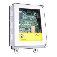
panel housed in the enclosure. The Metering Unit enclosure door has a window made of
clear polycarbonate. This allows the user to view various LED (or LCD) status indicators
while the door is closed. For more information, refer to the “Theory of Operation” section of
this manual.
There are two optional pc board assemblies that may be added onto the Main pc board in
the LKAT
2
Metering Unit:
• The Protection Extensions ( PE ) pc board assembly
• The Display pc board assembly.
One or both of these pc board assemblies may be added to an LKAT
2
Metering Unit in the
field. It is not mandatory that they be factory installed and/or calibrated. The optional pc
board assemblies may be calibrated on site, using the LKAT
2
Main Output as the reference
measurement.
2.4 ADDITIONAL INDICATOR AND OUTPUT DETAIL
As noted on the specifications page, the LKAT
2
System Metering Unit includes several
visual indicators. These include:
• Accuracy Diagnostics (operational status) LEDs: green = OK, red = system problem
(see Section - “Theory of Operation”).
• Over / Reverse Current Trip status LEDs: green = measured current does not exceed
the setpoint, red = measured current exceeds the setpoint.
• (Optional) Illuminated LCD digital display of measured current.
• Available via the Metering Unit output cable:
• Isolated signal output proportional to bus current being measured. This output may be
configured for various zero and full-scale values.
• Normally open and normally closed relay contacts indicate Accuracy Diagnostics (AD)
operational status (same as green and red LEDs).
• Normally open and normally closed relay contacts indicate over / reverse current trip
status (same as green and red LEDs).
The table below lists the features associated with the Main and PE pc board assemblies.
Table 2.1
Main and PE PC Board Assembly Features
with PE PC Board
Assembly
Operational Status LEDs & Relay Contacts
Overcurrent / Reverse Trip Status LEDs & Relay
Contacts
1 +2 for 3 total
Checking field calibration of LKAT
2
Systems requires use of a reference current transducer
with calibration accuracy of 0.1% full-scale or better. Contact DynAmp, LLC for calibration
of the LKAT
2
System. Refer to “Maintenance and Spare Parts” section for more information.

 Loading...