Installation, Operation and Service Manual LKAT
2
Portable
© 2018 DynAmp, LLC Page 22
047312 A
Hall IC Array
Head Half A
Signal
Conditioning
& Scaling
Hall IC Array
Head Half B
Signal
Conditioning
& Scaling
SENSOR HEAD
+12Vdc
+15Vdc
POWER SUPPLY PCB
Summing
Amplifier
Gain Adjust
Isolation
Current
Loop
DC Bias
Metering Unit PCB Assy
DC Bias
V
I
Comparator
Status LEDs
Relay Contacts
DC Bias
Comparator
Status LEDs
Relay Contacts
PROTECTION
EXTENSIONS
PCB (OPTIONAL)
Note: This PCB is very
similar to the Main PCB.
Display Gain &
Zero Adj.
RMS to DC
Digital Display
Display PCB (Optional)
19.99
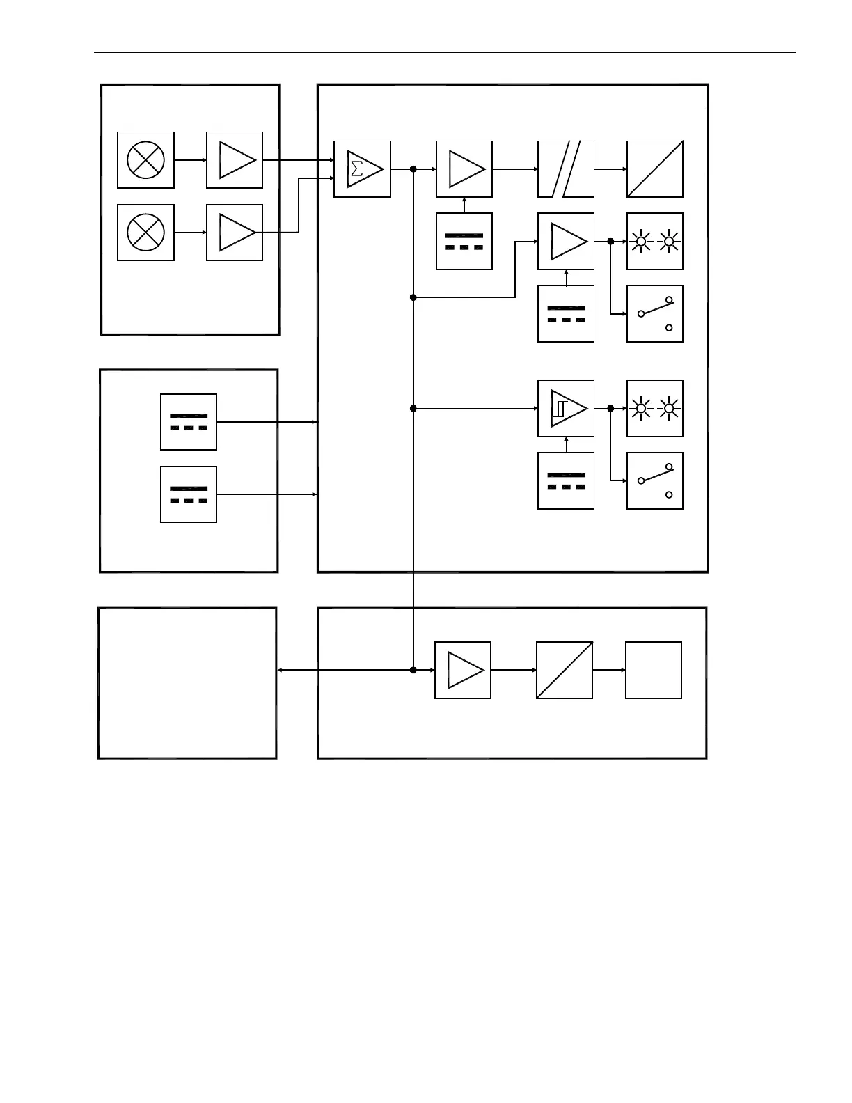
Figure 5.1
Block Diagram of the LKAT
2
System
5.3 SYSTEM FUNCTIONAL DESCRIPTION
The flux density associated with the primary current is sensed by arrays of Hall ICs in the
Measuring Head. The outputs of these devices are summed and filtered, then transmitted
to the Metering Unit where these signals are dc biased and scaled. The Accuracy
Diagnostics status LEDs and relay contacts are driven by a signal input that compares the
various Hall groups with voltage setpoints. When the Hall group signal exceeds the
reference, the green LED will go out and the red LED will illuminate. The relay coil will
change state under the same conditions. The Trip Setpoint LEDs and relay contacts
operate in a similar manner.