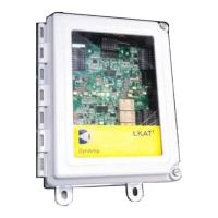
Installation, Operation and Service Manual LKAT
2
Portable
© 2018 DynAmp, LLC Page 15
047312 A
3. Determine the position where the Measuring Head will be installed.
4. Connect the head cable assemblies to the ITC Cable assembly using care to route the
head interconnection cables away from the bus and other high voltages.
5. Route the other end of the ITC cable to the Metering Unit.
6. Connect the ITC Cable assembly to the Metering Unit.
INSTALLATION USING MOUNTING CHANNELS
Refer to the Outline and Mounting LKAT2 4-pc Measuring Head drawing at the end of this
manual. The mounting hardware for this method consists of appropriately sized fiberglass
channels and rods along with brass washers and nuts.
The only tools required for mounting the measuring head with the fiberglass channels is an
appropriately sized adjustable wrench and cutters, if cable ties are used for holding cables,
etc.
“Running Bus Bar”
Refer to the drawing at the end of this manual “INSTALLATION – LKAT2P HEAD
W/MOUNTING CHANNELS “RUNNING” BUS BAR CONFIGUARTION”. Follow the steps
listed on the drawing.
When the Measuring Head is installed on the running (“horizontal”) bus, the head should be
installed such that the head interconnection cables exit to the bottom or sides of the bus to
the extent possible. This reduces the chances of ingress by pollutants and minimizes the
heating of the head electronics by the bus.
“Rising Bus Bar”
Refer to the drawing at the end of this manual “INSTALLATION – LKAT2P HEAD
W/MOUNTING CHANNELS “RISING BAR CONFIGURATION”. Follow the steps listed on
the drawing.
INSTALLATION USING MOUNTING ANGLES
The following is the recommended sequence for installing the Measuring Head, using
mounting angles and integral locking screws:
1. Refer to Outline & Mounting- LKAT
2
Measuring Head drawing.
2. Remove the backing from the adhesive foam strips on the mounting angles. Align the
mounting angles in position on the corners of the bus bar in the desired location.
3. Mate the two “A” head sides, pressing them together until the tubes bottom out on the
elbows. Install the quik pin on the outside of the square tubes adjacent to the place
where the head sides split apart.
4. Mate the two “B” head sides, pressing them together until the tubes bottom out on the
elbows. Install the quik pin on the outside of the square tubes adjacent to the place
where the head halves split apart.
5. Position the two “L-shaped” head halves around the bus and the mounting angle.
Mate the two halves, pressing them together until the tubes bottom out on the elbows.
6. Install the two remaining quik pins on the outside of the square tubes adjacent to the
place where the head halves split apart.
7. Tighten the bus mounting screws a few turns at a time in a circular pattern around the
aperture of the head, on the front side, then on back side of the head. A hex wrench is
included for adjusting the locking screws. For most applications, the head should be
centered on the bus bar. The bus mounting screws should press against the foam

 Loading...