Rev. 01/11 - 2.15 - TFXL-X
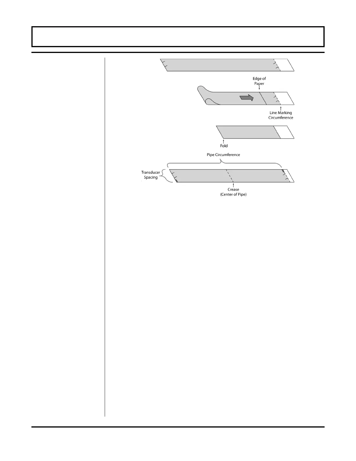
the template back around the pipe, placing the beginning of the
paper and one corner in the location of the mark. Move to the
other side of the pipe and mark the pipe at the ends of the
crease. Measure from the end of the crease (directly across the
pipe from the first transducer location) the dimension derived in
Step 2, Transducer Spacing. Mark this location on the pipe.
4. The two marks on the pipe are now properly aligned and
measured.
If access to the bottom of the pipe prohibits the wrapping of the
paper around the circumference, cut a piece of paper to these
dimensions and lay it over the top of the pipe.
Length = Pipe O.D. 1.57
Width = Spacing determined on page 2.6
Mark opposite corners of the paper on the pipe. Apply
transducers to these two marks.
5. For DTTN transducers, place a single bead of couplant,
approximately ½ inch (12 mm) thick, on the flat face of the
transducer. See Figure 2.2 on page 2.9. Generally, a silicone-
based grease is used as an acoustic couplant, but any grease-
like substance that is rated to not “flow” at the temperature that
the pipe may operate at, will be acceptable.
PART 2 - TRANSDUCER INSTALLATION
Figure 2.12
Bisecting the pipe circumference
 Loading...

