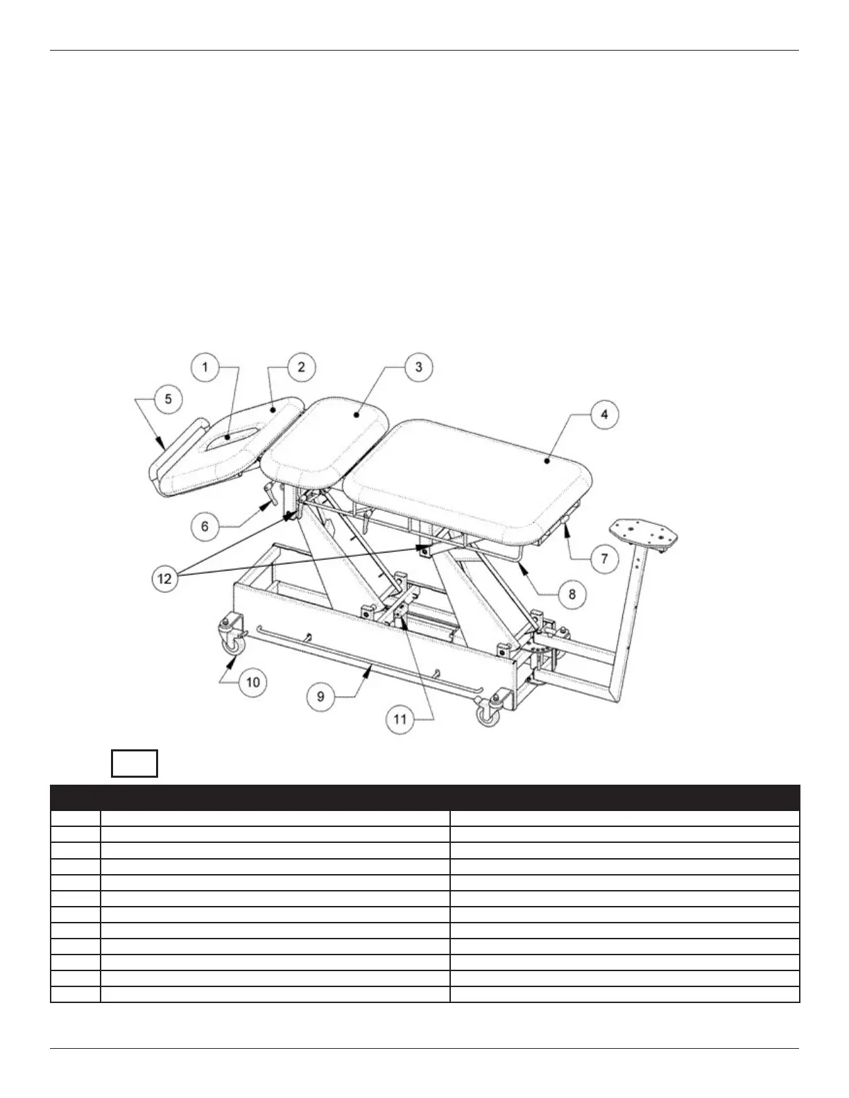
REPLACEMENT PARTS DIAGRAMS
DYNATRON® T3™ HI-LO TREATMENT TABLE & T4™ TRACTION TABLE | OPERATOR’S MANUAL REV. 10 | 4/4/2018 14
Replacement Parts Diagrams
No. Part Numbers Above Diagram Description
1 NHP(color) Nose Hole Plug
2 T4-TOP(color)-A Nose Hole Section
3 T4-TOP(color)-B Top Mid-Section
4 T4-TOP(color)-C Top Foot-Section
5 DT4PB Pull Bar
6 DTKNOB Li-back Handle (black)
7 T4SLIDELOCKHANDLE Traction Arm Handle and Sliding Mechanism
8 DP000075 Mobilization Strap Attachment System (Chrome Bar)
9 DP000072 Foot Switch Bar
10 DTCAS Two-Way Locking Casters
11 T34MPH Main Plug-in Housing
12 Pinch Point Labels Warning – Pinch Points
See part numbers and diagrams for insert View A on the following page.
REF