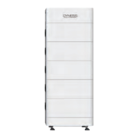
Tower ESS Unit User Manual
12
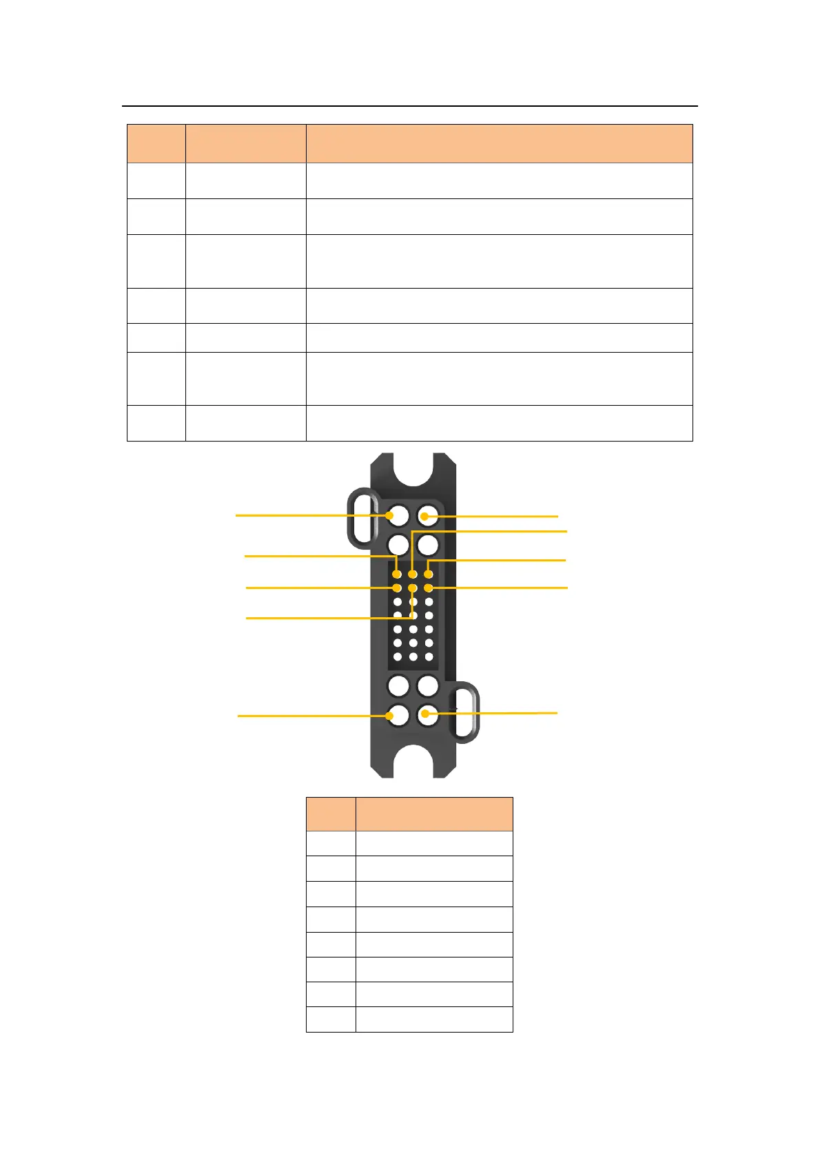
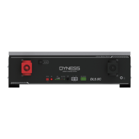
Table 2-5 Interface Definition
Long press this button to start the battery system
Connect battery system with Inverter positive terminal
EXT-CAN
Communication
Port
RJ45 communication port between the battery system and
inverter
Connect battery system with Inverter negative terminal
Turn on the switch to power the BMS system
The master switch of the battery system,you must switch on it
before switching on power on&power wake switch; Short
circuit protection.
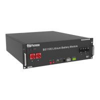
Composite
connector-Socket
Battery module output and communication interface
///