

J
Jorge WilliamsSep 23, 2025
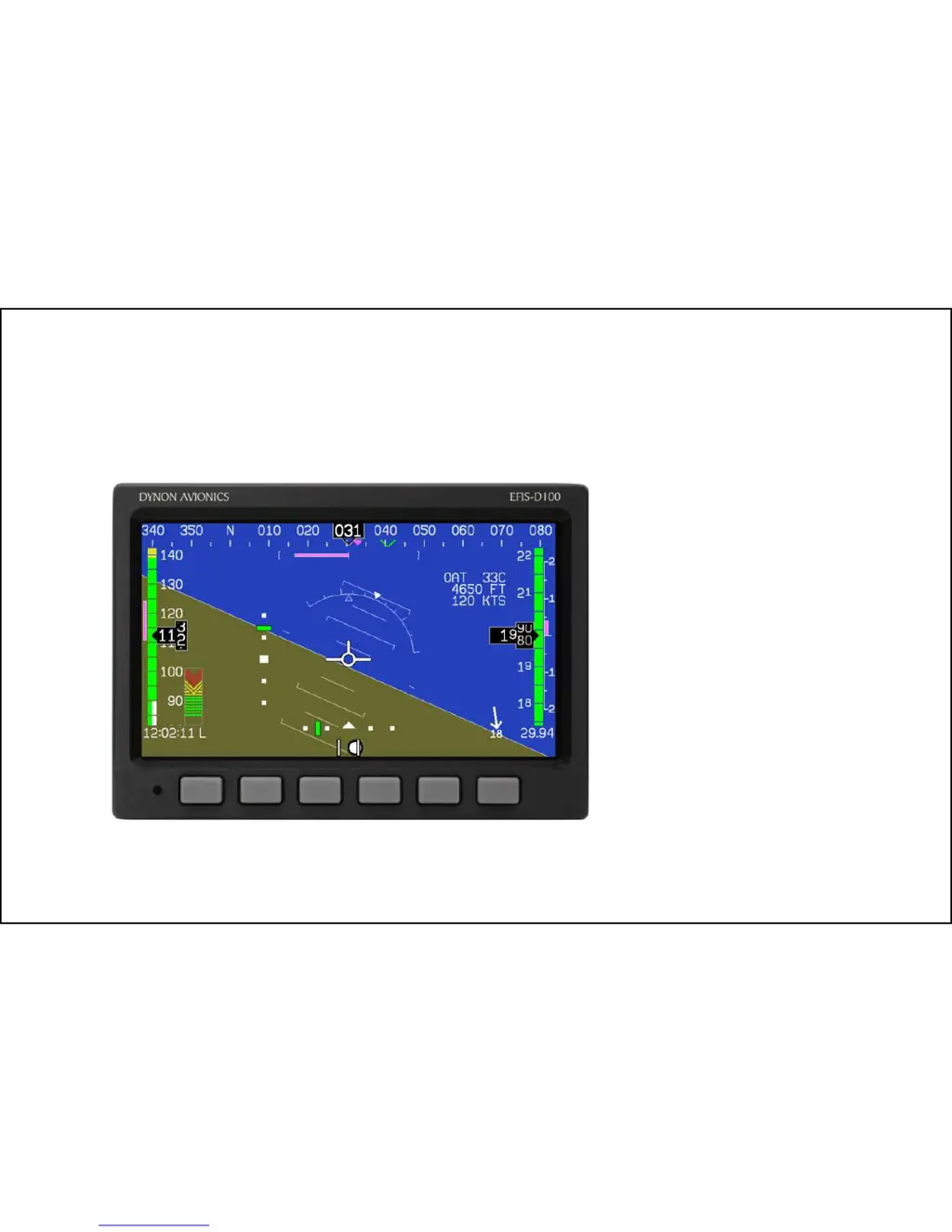
What should I do if my Dynon Avionics Display EFIS-D100 indicates an over temperature condition?
- TTimothy BellSep 23, 2025
If your Dynon Avionics Display EFIS-D100 indicates an over-temperature condition, provide additional cooling to the instrument.

