Do you have a question about the E-FLITE Stearman PT-17 15e ARF and is the answer not in the manual?
Lift and pull the cockpit hatch aft to disengage tabs and remove it.
Install grommets and bushings into the rudder and elevator servos.
Center servos using radio or MatchMaker, trim servo horns.
Place servos in fuselage cutouts and mark mounting holes.
Use a 1/16-inch drill bit in a pin vise to drill servo mounting holes.
Use a ruler to mark the center and sides of the stabilizer's trailing edge.
Use a square to transfer the centerline to the stabilizer's leading edge.
Insert the stabilizer into the fuselage and align with marks.
Mark the bottom of the stabilizer where it meets the fuselage sides.
Fold hinges to form a crease and insert them into the elevator.
Insert hinges into the stabilizer, angling the elevator as shown.
Apply CA to hinges and joints to secure the stabilizer to the fuselage.
Separate tailwheel shaft, install it in the fuselage and rudder.
Insert pushrods into guide tubes, connect to servo arms with keepers.
Drill outer hole in rudder servo arm and inner hole in elevator servo arm.
Bend the rudder pushrod so the threaded end is 1/2-inch from the fuselage.
Cut corner off control horn, connect clevis, mark and drill holes.
Attach rudder control horn and backing plate with screws.
Connect elevator clevis, mark servo horn holes with pen.
Drill holes for elevator control horn, install horn and backing plate.
Insert landing gear into fuselage, align mounting holes.
Use bolts and washers to secure landing gear, apply threadlock.
Attach cabane struts to fuselage using Allen bolts and threadlock.
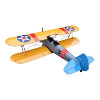
CG is 3-1/4 to 3-3/4 inches behind the leading edge of the upper wing.
Use a balancing device or fingertips to check balance at CG range.
Add 2-4 ounces of nose weight if needed, conforming it to cowling.
Use transmitter settings to achieve specified throw measurements for controls.
Perform a ground-range check of the radio system before each flight.
Check control surfaces move correctly and with recommended throws.
Ensure control horns, servo horns, and clevises are secure and in good condition.
User is responsible for operating the model safely and without endangering others.
Operate model in open areas, away from traffic, people, and hazards.
Keep chemicals, small parts, and electrical items away from children. Avoid moisture.
| Is Assembly Required | Yes |
|---|---|
| Skill Level | Intermediate |
| Recommended Environment | Outdoor |
| Radio System | 4+ channel radio system |
| Servos | 4 standard servos |
| Speed Control | 40A brushless ESC |
| Recommended Battery | 3S 11.1V 2200mAh LiPo |
| Material | Balsa and plywood |
| CG (center of gravity) | 3.5 in (89 mm) back from leading edge of wing |