Do you have a question about the E Instruments E8500 Plus and is the answer not in the manual?
Lists the different types of gas sensors available for the analyzer.
Describes the probe and sample line options for gas extraction.
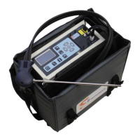
Details the standard equipment included with the E8500 Plus analyzer.
Provides step-by-step instructions for powering on and preparing the analyzer.
Offers recommendations for safe operation and maintenance of the analyzer.
Lists common autozero errors and their potential causes and resolutions.
Details the types of probes and sampling lines used for gas extraction.
Explains the system that removes condensation and soot from the sample gas.
Details the function and adjustment of the thermoelectric chiller for sample conditioning.
Details the seven electrochemical sensors and their principles.
Covers NDIR sensors for CO, CO2, and hydrocarbons with specifications.
Describes the PID sensor for VOC detection and its specifications.
Details ambient temperature, stack temperature, and draft/velocity sensors.
Explains how the analyzer displays and uses date and time information.
Details the list of fuels the analyzer can use and how to select them.
Describes how to toggle between Fahrenheit and Celsius for temperature readings.
Explains how to select units for toxic gases (PPM, MGM, #/B, GBH).
Details the options for displaying pressure units (inWC, mbar, mmWC, kPa).
Describes the selection between % and ppm units for hydrocarbon measurements.
Explains how to set the oxygen reference for pollutant concentration corrections.
Details the different pump modes (AUTO, SAMPLE, DILUTE, PURGE, OFF).
Configures dilution pump power and thermoelectric chiller temperature.
Sets CO threshold for dilution and purge, and NDIR usage.
Adjusts display contrast, baudrate, and engine thermal efficiency.
Selects units for velocity (FPS, MPS, CFM, CMM) and notes that velocity and draft cannot be measured simultaneously.
Estimates cross-section area for accurate stack gas flow measurements.
Stores one set of emissions data into the currently selected tag.
Displays an index of internal storage tags and allows selection of a new tag.
Begins a period of data averaging with values stored periodically.
Configures periodic data storage interval and starts the storage process.
Allows viewing, naming, and erasing stored data tags.
Prints a test record of the current stack parameters.
Logs combustion parameters like temperature, oxygen, CO, and efficiency.
Selects the interval between each log entry for the printer.
Prints data stored in the analyzer's memory, tag by tag or all tags.
Customizes printout appearance and customer information.
Toggles the printer's motor on and off to advance paper.
Covers zeroing all sensors, thermocouples, and checking autozero errors.
Accesses sensor history, ambient temperature, and preheat temperature settings.
Configures autozero/span times and enables span lockout for safety.
Details autozeroing and span calibration procedures for sensors.
Outlines the key strokes for calibrating electrochemical sensors.
Details the procedure for calibrating NDIR sensors.
Enhances analyzer performance with features like monitoring and plotting.
Explains how to replace the disposable fiber line filter and condensation disk filter.
Describes how water vapor condenses and is removed by the chiller and pump.
Provides guidance on replacing gas sensors and required waiting periods.
Details the procedure for installing pre-calibrated sensors and setting factors.
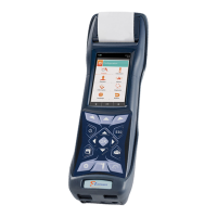
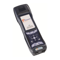
Details analyzer's physical attributes and power system specifications.
Covers display, wireless printer, and software details.
Outlines internal memory storage and connectivity specifications.
Explains calculations for combustion efficiency and excess air.
Details calculations for NOx, various emissions, and stack gas flow rate.
Provides steps for updating the analyzer's internal software (firmware).
| Brand | E Instruments |
|---|---|
| Model | E8500 Plus |
| Category | Measuring Instruments |
| Language | English |