E-max Gaming Corporation, Inc.
13
E-MAX
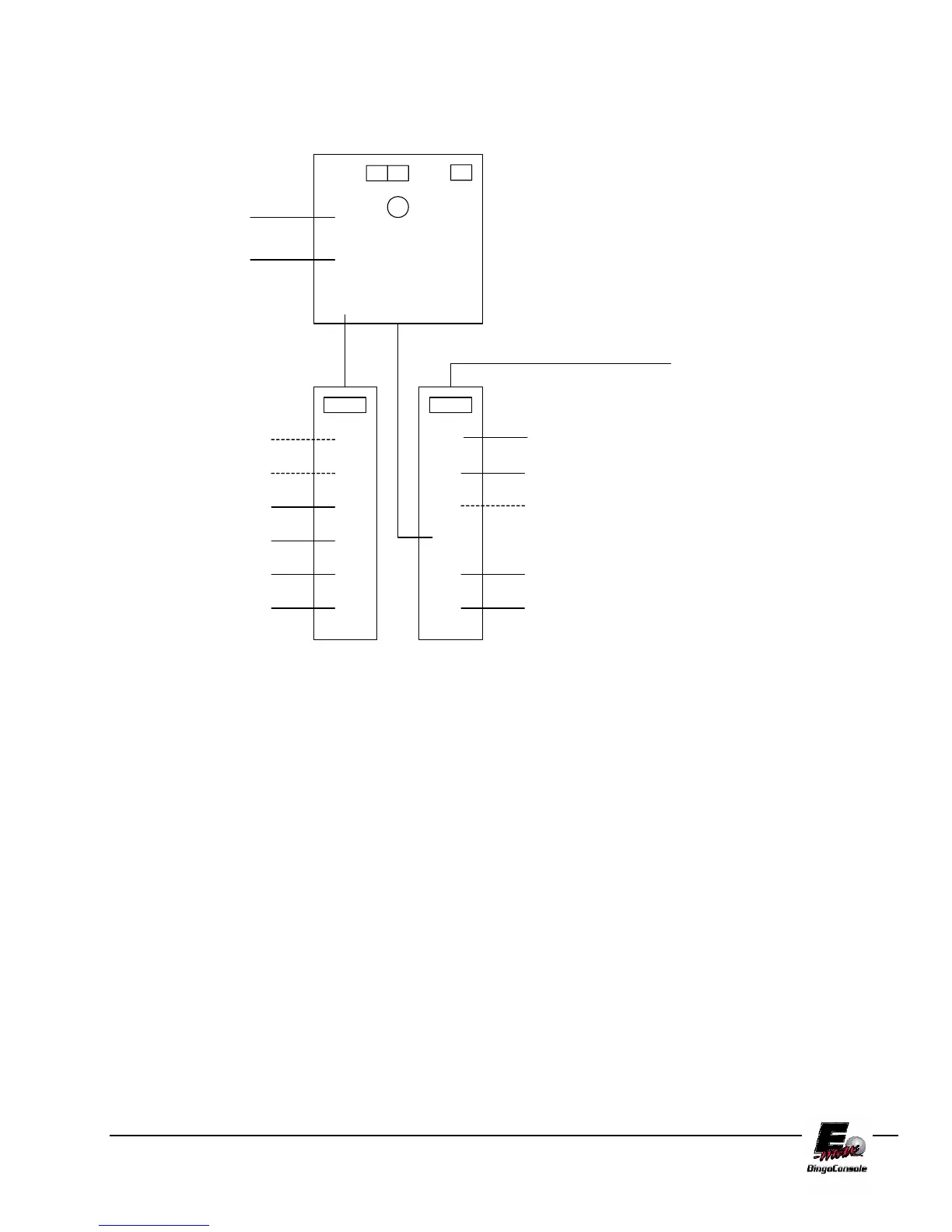
AC POWER CONNECTIONS
OPERATOR
DISPLAY
RF MOD #1
1
3
2
6
5
4
1
3
2
6
5
4
1
3
2
6
5
4
UPS
DELL
OUTLET STRIP #1
(Graphics panel side)
OUTLET STRIP #2
(Operator side)
RF MOD #2
LIGHT
FAN
NETWORK DEVICE #1
DATA ROUTER
BLOWER #1
BLOWER #2
NETWORK DEVICE #2
DON'T USE
PRINTER OR VCR
AC POWER IN
DON'T USE
DON'T USE
DON'T USE
UPS SOCKETS
1,2,3 ARE BACKUP
UPS SOCKETS
4,5,6 ARE NON
BACKUP
POWER
INPUT
Figure 2.5
2.5 Powering up the Console
1. The main power “ON” switch for the electronic console is located on Outlet Strip #2 (Figure 2.5). After
turning on, press the button on the front of the UPS (Figure 2.6).
For maximum battery backup time allow the UPS to charge for a full eight hours prior to console
use.