Page G-4
MOTOR & MOTOR BRAKE
Repair and Service Manual
Read all of Section B and this section before attempting any procedure. Pay particular attention to all Notices, Cautions, Warnings and Dangers.
B
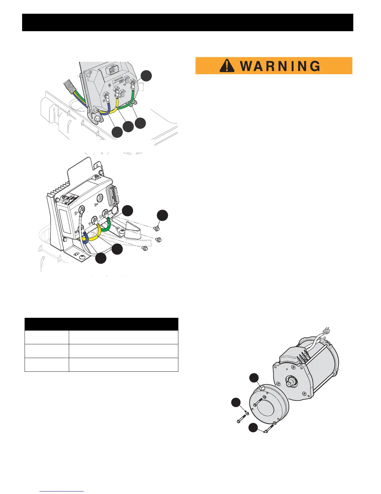
tighten the terminal screws (27) & (28). .
Fig. 8 Motor to Controller Connections
18.Connect the negative (-) battery cable, BL-, to the bat-
tery pack.
MOTOR BRAKE
The motor brake may be removed with the motor still in
the vehicle or the motor and motor brake can be removed
from the vehicle as a unit. If the motor and motor brake
are to be removed as a unit see the previous section for
instructions on the motor removal and installation.
The only service items for the motor brake is the entire
motor brake assembly.
Disconnect the negative (BL-) battery cable
with an insulated wrench before attempting to
disconnect wires from the motor (see safety
procedures in SAFETY section of this manual).
Tool List Qty.
Ratchet ........................................................................1
Torque Wrench, in. lbs. ................................................1
Socket, 10 mm.............................................................1
Socket, 9/16"................................................................1
Torx Bit, T-27................................................................1
Insulated Wrench, 9/16"...............................................1
Wheel Chocks..............................................................4
Removal
1. Chock the rear wheels of the vehicle.
2. Raise and remove seat bottom.
3. Using an insulated wrench, disconnect the negative
(-) battery, BL-, cable from the battery.
4. Drain the stored energy from the controller. Place the
Run/Tow switch in the Run position, turn the key
switch to reverse, wait for the reverse warning indica-
tor to become silent turn the key switch to the off posi-
tion and remove the key from the switch.
5. Remove the two Torx head screws and the rear
access cover from the bagwell area.
6. Disconnect wire harness from motor brake.
7. Remove three hex head bolts (32) and lock washers
(33) from the motor brake assembly (31).
Fig. 9 Motor Brake
ITEM TORQUE SPECIFICATION
2 53 - 79 in. lbs (6 - 9 Nm)
27 53 - 71 in. lbs (6 - 8Nm)
28 80 - 97 in. lbs (9 - 11Nm)
23
24
25
27
OLD CONTROLLER ASSEMBLY
3
NEW CONTROLLER ASSEMBLY
23
28
25
24


 To Next Page