A
ENGINE TOP END DISASSEMBLY
Page A-1
Kawasaki Engine Shop Rebuild Manual
ENGINE TOP END
Tool List Qty. Required
Compression Gauge, 20 kgf/cm²:
E-Z-GO Part No. N/A .................................................. 1
Valve Seat Cutter, 45° - 32:
E-Z-GO Part No. 608665 ............................................ 1
Valve Seat Cutter, 45° - 35:
E-Z-GO Part No. 608666 ............................................ 1
Valve Seat Cutter, 32° - 35:
E-Z-GO Part No. 608667 ............................................ 1
Valve Seat Cutter, 32° - 38.5:
E-Z-GO Part No. 608668 ............................................ 1
Valve Seat Cutter Holder, 7:
E-Z-GO Part No. 608669 ............................................ 1
Valve Seat Cutter Holder Bar:
E-Z-GO Part No. 608670 ............................................ 1
Compression Gauge Adapter, M14 × 1.25:
E-Z-GO Part No. N/A .................................................. 1
Keep your work area clean and well organized while performing
the operations described in this manual. This will help prevent
accidents and reduce the possibility of mistakes that could
damage or impair the performance of the engine.
Crankshaft and balancer shaft bearings should be cleaned and
inspected, and removed only if they appear to be damaged or
excessively worn. Remove bearings that are pitted, nicked,
burred, discolored or that rotate roughly or noisily.
Because some mating parts with wear surfaces were machined
together when the engine was manufactured, or have estab-
lished wear patterns during operation, the reassembly of engine
parts in their original positions and orientations, with their origi-
nal mating parts, is critical to the performance and life expectan-
cy of the engine. Mark and sort all parts as they are
disassembled so that they will be reassembled and installed in
their original positions.
CYLINDER HEAD
Remove Cylinder Head
A. Several components must be removed in order to
gain access to the cylinder head (for example carbu-
rator and exhaust). Refer to the service manual of
your vehicle for removal procedures.
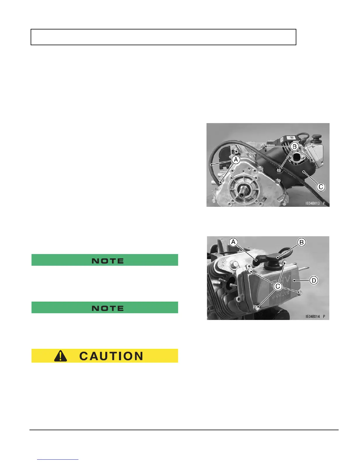
B.
Remove clamp and hose [A], bolts [B], and engine
shroud [C].
C.
Remove spark plug cap [A], dipstick [B], valve cover
bolts [C], and valve cover [D].
D. Position the crankshaft at TDC of the end of the com-
pression stroke.