C
ENGINE MEASUREMENTS
Page C-1
Kawasaki Engine Shop Rebuild Manual
ENGINE MEASUREMENTS AND
SPECIFICATIONS
Tool List Qty. Required
Compression Gauge, 20 kgf/cm²:
E-Z-GO Part No. N/A .................................................. 1
Compression Gauge Adapter, M14 × 1.25:
E-Z-GO Part No. N/A .................................................. 1
Valve Seat Cutter, 45° - 35
E-Z-GO Part No. 608666 ............................................ 1
Valve Seat Cutter, 32° - 38.5
E-Z-GO Part No. 608668 ............................................ 1
Valve Seat Cutter, 45° - 32
E-Z-GO Part No. 608665 ............................................ 1
Valve Seat Cutter, 32° - 35
E-Z-GO Part No. 608667 ............................................ 1
Valve Seat Cutter Holder, 7
E-Z-GO Part No. 608669 ............................................ 1
Valve Seat Cutter Holder Bar
E-Z-GO Part No. 608670 ............................................ 1
All engine parts must be thoroughly cleaned, and free of all dirt,
oil, grease, carbon deposits or residue of any kind before begin-
ning this section. It is especially important that your work area
be clean and well organized while performing the operations
described in this section.
In some cases, time may be saved by setting measuring instru-
ments at limit specifications and using them as “go-no-go” fix-
tures. Check preset instrument fit in bores, on shafts, etc. to
determine part acceptability. We recommend that parts bound
to be acceptable but near limits be replaced if the engine will
see high usage.
Check micrometers for proper calibration before beginning the
operations described in this section.
Using Telescoping Gauges and Hole
Gauges
Telescoping gauges and hole gauges are “transfer-type”
measuring instruments. They are not calibrated and are
used to record a distance, which is then transferred to a
micrometer for measurement.
Position the gauge in the hole or bore and “set” the tele-
scoping arms or ball to its true diameter. Make sure that
the handle of the gauge is in line with the centerline of
the hole or bore.
Lock and remove the gauge. Measure its setting with a
micrometer.
CYLINDER HEAD
Measure Cylinder Compression
A. Thoroughly warm up the engine so that the engine oil
between the piston and the cylinder wall will help seal
compression as it does during normal running.
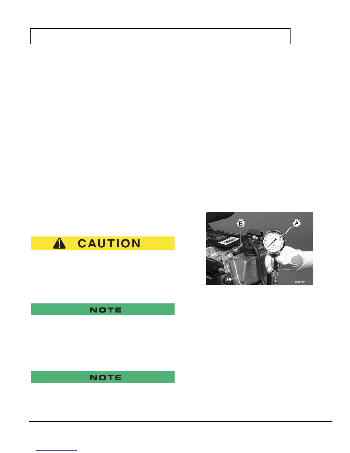
B.
Stop the engine, remove the spark plug, and attach a
compression gauge [A] firmly into the spark plug hole
[B].
Special Tools
Compression Gauge, 20 kgf/cm²
E-Z-GO Part No. N/A
Compression Gauge Adapter, M14 × 1.25 [B]
E-Z-GO Part No. N/A
C. Using the starter, turn the engine over with the throt-
tle fully open until the compression gauge stops ris-
ing; this is the highest compression reading
obtainable.
Cylinder Compression
Usable Range: 880 ~ 1 080 kPa (9 ~ 11 kgf/cm², 128 ~
156 psi) @500 ~ 700 r/min (rpm)