BRAKES - REAR MECHANICAL
Page K-13
Repair and Service Manual
Read all of Section B and this section before attempting any procedure. Pay particular attention to all Notes, Cautions and Warnings
9. Measure the brake shoe thickness.
Measure at the most worn area. Brake shoe thick-
ness must never be less than .06" (1.5 mm) at any
point on the shoe. It is normal for the shoes to show
more wear at the leading and trailing edges (Ref Fig.
16 on page K-13). If the brake shoe thickness is
approaching .06" (1.5 mm), it is recommended that
the shoes be replaced. It is recommended that the
brake shoe springs and brake adjusters be replaced
when installing new brake shoes.
10.Inspect the brake shoe springs.
Be sure that they are not broken or damaged and are
correctly installed. The hooked end of the adjuster
spring is inserted through the front of the front shoe
and the opposite end hooked to the adjuster with the
hook end facing out. The brake shoe springs must be
installed with the light spring closest to the adjuster
mechanism with the hook installed down through the
rear brake shoe and up through the front brake shoe.
The heavy top spring is installed with both spring
hooks installed down through the brake shoes (Ref
Fig. 17 on page K-13).
11. Repeat procedure at the opposite wheel brake.
12.Check/adjust brake pedal free travel.
Whenever the brake system is serviced or requires a
parts replacement, the brake pedal free travel must
be checked and adjusted. See ‘Adjusting Brake Pedal
Free Travel’ on page K-14. This includes all linkage and
wheel brake components.
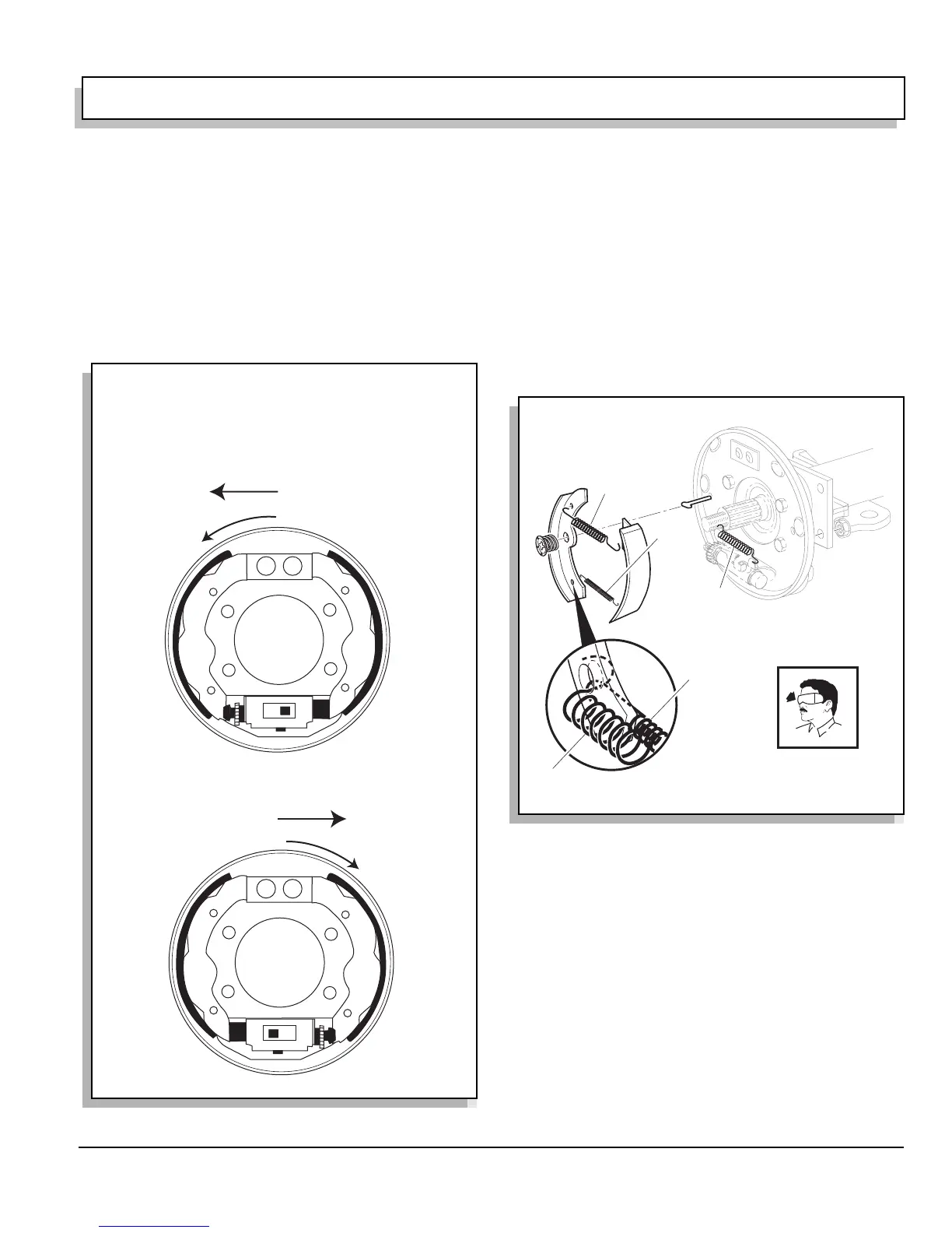
Fig. 16 Brake Shoe Wear
Forward
Forward
A
A
B
B
C
C
D
D
Drum Rotation
Drum Rotation
Driver side
Passenger Side
The pattern of normal brake shoe wear is
shown in quadrant ‘A’, ‘B’, ‘C’ & ‘D’ with
quadrant ‘A’ showing the most wear.
Quadrant ‘B’ will show the second most wear.
Fig. 17 Orientation of Brake Shoe Springs
Heavy Shoe
Spring
Light
Shoe
Spring
Adjuster
Spring
Adjuster
Sprin
Light
Shoe
Spring
 Loading...


