BATTERY CHARGER
Page L-3
Repair and Service Manual
Read all of Section B and this section before attempting any procedure. Pay particular attention to all Notes, Cautions and Warnings
TROUBLESHOOTING
Tool List Qty. Required
DVOM ......................................................................... 1
Phillips screwdriver ..................................................... 1
A simple but effective method of troubleshooting a bat-
tery charger that does not operate is to follow the
sequenced troubleshooting procedures (Ref Fig. 6 on
page L-4).
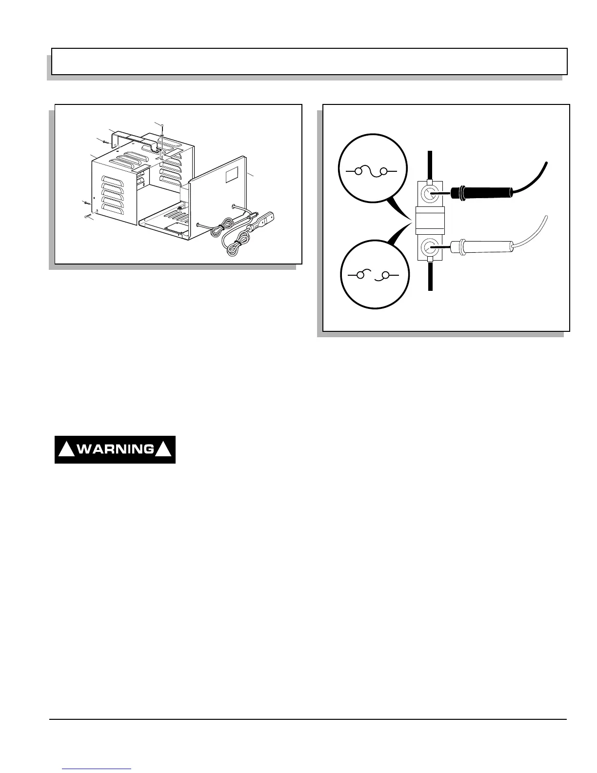
Continuity Checks
Before attempting to per-
form a continuity check,
disconnect the battery
charger from both AC and DC power sources.
To check for continuity, set the DVOM (digital volt ohm
meter) to K ohms setting and select ‘Continuity’. The
meter will give an audible signal when it detects continu-
ity. If the meter does not have a continuity setting, set the
meter then to K ohms, the meter will indicate “0” when
continuity is detected (Ref Fig. 5 on page L-3).
Diode Test Procedure
Tool List Qty. Required
DVOM.......................................................................... 1
To test the diode, disconnect the battery charger AC
power cord. With the DVOM set at highest ohms range
available, place probes on diode as shown (Ref Fig. 7 on
page L-5). A reading other than that shown indicates the
diode is bad. Replace as necessary.
COMPONENT REPLACEMENT
When replacing components, reinstall in reverse order of
disassembly. Pay particular attention to any wiring that
may have been disconnected, being sure to replace in
original position.
Fig. 4 Opening the Charger
1
2
5
5
3
4
6
! !
Fig. 5 Continuity Check
(Fuse shown as typical
example of performing
continuity check)
(-) Probe
(+) Probe
Good
fuse
"Beep"
Blown
fuse
No
"Beep"
Continuity
No Continuity
 Loading...


