FRONT SUSPENSION AND STEERING
Page E-11
Repair and Service Manual
Read all of Section B and this section before attempting any procedure. Pay particular attention to all Notes, Cautions and Warnings
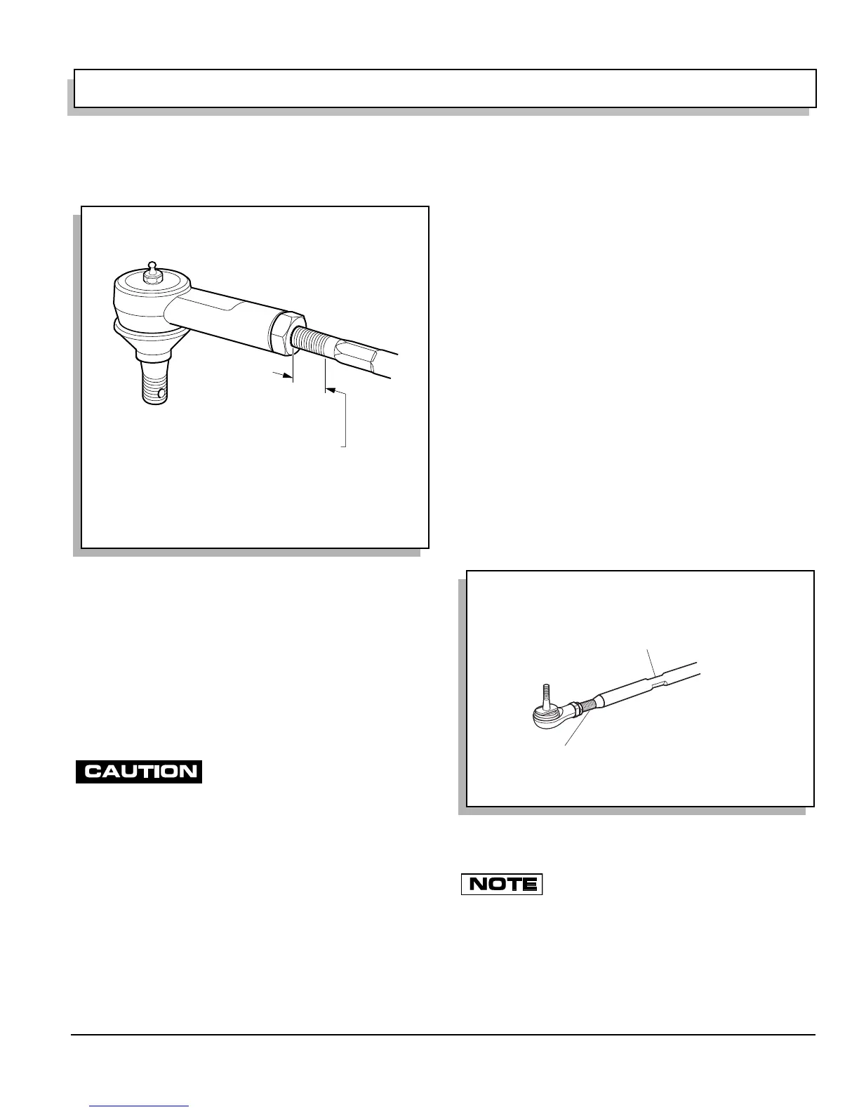
To install new rack ball joint close to its correct position,
measure amount of threads exposed from jam nut (Ref
Fig. 13 on page E-11).
Loosen jam nut (4) and remove rack ball joint from rack
extension (5).
Using measurement made earlier, thread jam nut and
new rack ball joint to previous location on rack extension
and set jam nut hand tight.
Attach rack ball joint to spindle arm. Tighten castellated
nut (3) to 36 ft. lbs. (50 Nm) torque and continue to
tighten as needed to insert new cotter pin (2). Maximum
torque is 50 ft. lbs. (70 Nm).
After replacing or servicing steering
components, always verify that an 1/8"
gap exists between large hex of rack extension and rack and pin-
ion unit when steering is turned fully to the right forcing passen-
ger spindle arm against front axle (Ref Fig. 21 on page E-16).
Check for proper rack extension-to-rack and pinion unit
clearance before tightening jam nut (4) to 35 - 45 ft. lbs.
(47 - 61 Nm) torque. See ‘Checking/Adjusting Rack
Extension-to-Rack and Pinion Unit Clearance’ on page
E-15.
Install passenger side front wheel per WHEELS AND
TIRES section and lower vehicle per SAFETY section.
Check front wheel alignment and adjust if necessary.
See ‘Wheel Alignment’ on page E-3.
Tie Rod Inspection/Replacement
Tool List Qty. Required
Tape measure.............................................................. 1
Wrench, 3/4"................................................................ 1
Wrench, 9/16".............................................................. 1
Needle nose pliers....................................................... 1
Wrench, 11/16"............................................................ 1
Ball joint separator....................................................... 1
Plastic faced hammer..................................................1
Socket, 11/16", 1/2" drive ............................................1
Torque wrench, 1/2" drive, ft. lbs. ................................ 1
Crowfoot socket, 3/4", 1/2" drive ................................. 1
Grasp the tie rod (8) at ball joints (6) and check for any
vertical motion which would indicate a worn condition
and require replacement (Ref Fig. 12 on page E-10).
To remove tie rod, loosen wheel(s) and lift and support
front of vehicle per SAFETY section.
Remove front wheel.
To install new tie rod ball joint close to its correct position,
measure the exposed thread length from jam nut (Ref
Fig. 14 on page E-11).
Loosen jam nut (7) at threaded tube (8).
To hold threaded tube while loosening jam nut,
use a wrench on the center, flat section of tube
(Ref Fig. 12 on page E-10).
The tie rod has different threads on each end. The end with the
flat area on the threaded tube has left hand threads (clockwise
to loosen) while the end without the flat has conventional right
hand threads (counter-clockwise to loosen) (Ref Fig. 14 on
page E-11).
Fig. 13 Rack Ball Joint Installation
Measure exposed thread length
and use length to position new
ball joint at same location
Fig. 14 Tie Rod Replacement
Measure threads showing for length
to position new ball joint at same location
Flat section towards end identifies
end with left hand threads
 Loading...


