FRONT SUSPENSION AND STEERING
Page E-14
Repair and Service Manual
Read all of Section B and this section before attempting any procedure. Pay particular attention to all Notes, Cautions and Warnings
Check front wheel alignment and adjust if necessary.
See ‘Wheel Alignment’ on page E-3.
Rack and Pinion Unit Disassembly and
Inspection
Tool List Qty. Required
Vice .............................................................................1
Socket, 3/8", 3/8" drive................................................1
Ratchet, 3/8" drive....................................................... 1
Wrench, 11/16"............................................................ 1
Wrench, 3/4"................................................................ 1
Wire cutter................................................................... 1
Retaining ring pliers..................................................... 1
Shop towel................................................................ AR
CITGO Lithoplex MP No. 2 grease........................... AR
Wire tie, 8" long ...........................................................1
Wire tie, 10" long ......................................................... 1
Torque wrench, 3/8" drive, in. lbs. ...............................1
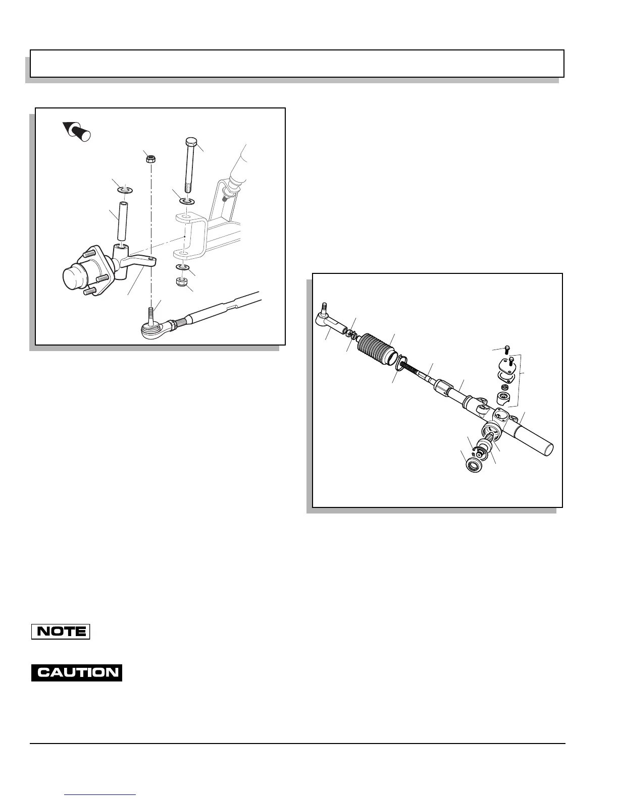
The rack and pinion gears are not serviceable
items. If they are found to be damaged or
excessively worn, a new rack and pinion unit must be installed.
Secure rack and pinion unit in vice by
the mounting ears only. The rack and
pinion unit is made of aluminum and can be damaged if held oth-
erwise.
Remove rack and pinion unit from vehicle. See ‘Rack
and Pinion Unit Replacement’ on page E-15. Anchor in
vice by clamping on the mounting ears of the unit.
Disassemble rack and pinion unit (1) by first removing
screw (13) and tensioner (2) to relieve pressure on rack
(3) and pinion (4) (Ref Fig. 19 on page E-14). Loosen jam
nut (5) and remove rack ball joint (6) from rack extension
(7). Cut wire ties (8, 14) securing bellows (9) and slide
bellows off rack extension. Pull rack (3) from unit (1).
Remove pinion seal (10). See ‘Pinion Seal Replacement’
on page E-12. Remove internal retaining ring (11) from
rack and pinion unit and pull out pinion (4) and ball bear-
ing (12) as an assembly.
Clean rack, pinion and housing. Inspect gear teeth, bear-
ing surfaces and grease seal surfaces of rack and pinion
for excessive wear or damage. If any is found, the rack
and pinion unit must be replaced as an assembly. See
‘Rack and Pinion Unit Replacement’ on page E-15.
If rack and pinion pass inspection, clean them, tensioner
and housing thoroughly and lubricate for assembly. Use
grease specified in tool list.
Assemble rack and pinion unit by first installing pinion in
reverse order of removal making sure to lubricate pinion
seal lip prior to installing seal. See ‘Pinion Seal Replace-
ment’ on page E-12. Insert rack into rack and pinion unit.
Turn pinion clockwise to help pull rack in if necessary.
Install bellows and secure to rack extension with wire tie
(8). Do not secure large end of bellows to rack and pin-
Fig. 18 Spindle Replacement
Front of Vehicle
7
5
9
10
3
2
4
8
6
Fig. 19 Rack and Pinion Unit Disassembly
10
11
12
1
2
3
8
9
6
5
7
4
13
14
 Loading...


