F
ELECTRONIC SPEED CONTROL (36V)
Page F-1
Repair and Service Manual
Read all of Section B and this section before attempting any procedure. Pay particular attention to all Notes, Cautions and Warnings
GENERAL
The Electronic Speed Control system consists of two
separate units, the pedal box and the controller.
Pedal Box
The Pedal Box assembly is a modularized unit that con-
tains the accelerator pedal, return spring and an
enclosed box that contains the pedal position micro
switch and a solid state Inductive Throttle Sensor (ITS)
that is activated by a moving plunger attached to the
accelerator pedal.
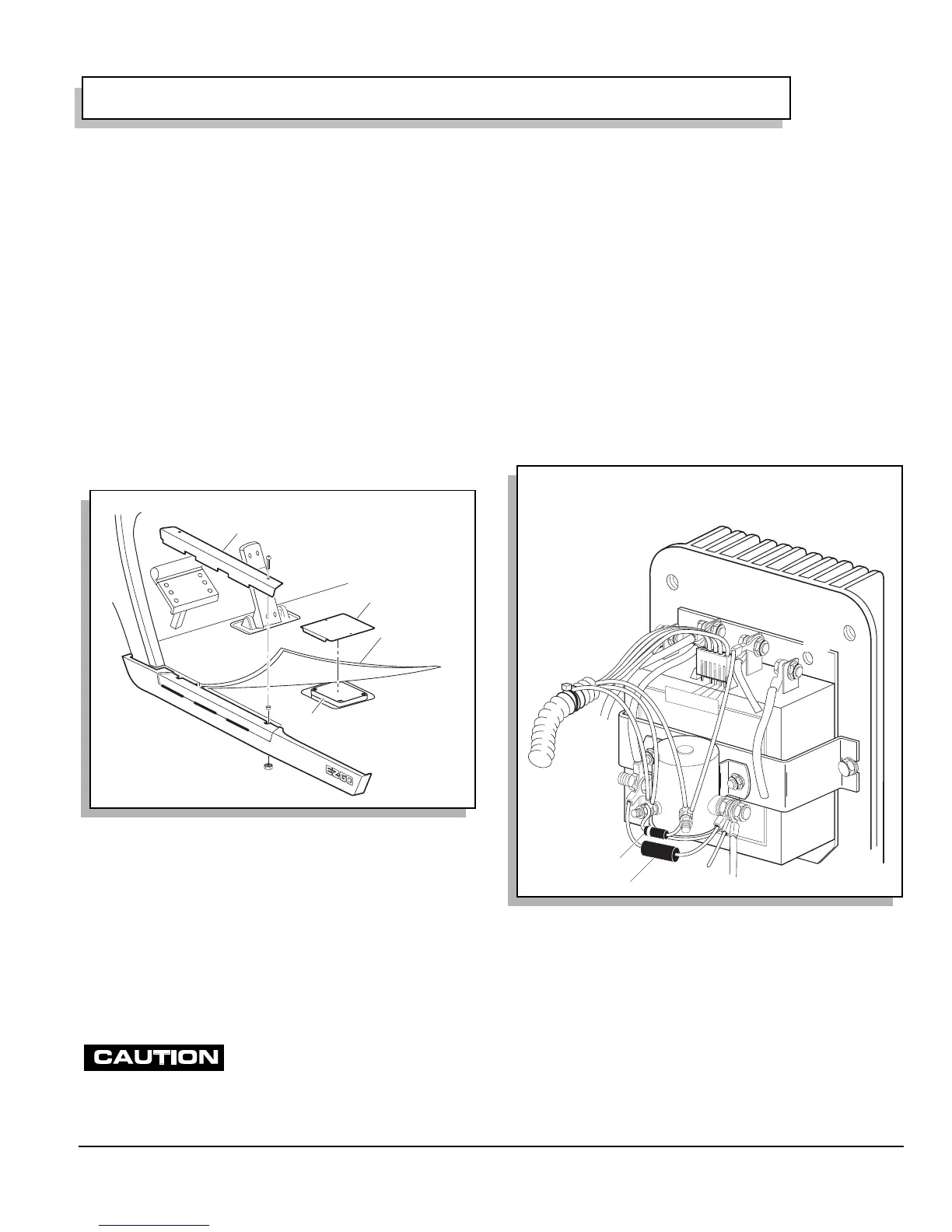
To access the pedal box, remove the rocker panel, lift the
floor mat, and remove the access cover from the floor
(Ref Fig. 1 on page F-1). The ITS and plunger are
accessed by removing the top cover from the enclosed
pedal box.
Controller
The Controller is a solid state unit activated by a sole-
noid. Both are located under the seat on the passenger
side of the vehicle.
A diode is positioned between the two coil terminals of
the solenoid. Its orientation is critical. The cathode side of
the diode, identified with a silver band, is oriented to the
solenoid terminal with the red wire attached (Ref Fig. 2
on page F-1).
If the diode is incorrectly oriented, the
pedal box micro switch and the direc-
tion selector micro switch may be permanently damaged.
The pedal box and controller are connected by a four pin
connector that is located under the seat within the black
plastic environmental cover.
The controller is wired to the batteries and develops a
regulated power supply for the ITS. The plunger position
relative to the ITS varies the voltage which is fed back to
the controller which interprets the change in voltage and
supplies the appropriate power to the motor.
The ITS unit and the controller are both solid state units
that contain no user serviceable parts. The testing pro-
cedures are designed to test the basic functionality
of the power and control wiring systems. Once the
functionality of the wiring has been confirmed, the
remaining tests are used to identify which of the compo-
nents (controller or ITS) must be replaced.
GENERAL TROUBLESHOOTING
Tool List Qty. Required
Floor jack..................................................................... 1
Jack stands ................................................................. 2
Wheel chocks.............................................................. 4
Jumper wire (with alligator clips) ................................. 1
DVOM.......................................................................... 1
Fig. 1 Access to Pedal Box
Rocker Panel
Floor Mat
Access Cover
Pedal Box
PA
R
K
Fig. 2 Controller and Solenoid
M-
B-
1
2
3
4
5
6
B+
ee Wiring Diagram at end of section for wire connections
Diode
 Loading...


