N
REAR AXLE
Page N-1
Repair and Service Manual
Read all of Section B and this section before attempting any procedure. Pay particular attention to all Notes, Cautions and Warnings
Rear Axle Removal
The rear axle assembly is
top heavy. To reduce the
possibility of personal
injury while removing the rear axle, be sure to support
the axle and motor assembly when removing the
springs.
If no lifting device is available, a second person
should hold the motor in the correct position until the
springs are removed. Both persons should remove
the rear axle and motor assembly.
Disconnect the negative (BL-) battery cable with an
insulated wrench before attempting to remove wires
from the motor (see safety procedures in SAFETY
section of this manual). The shorting of motor wires
could cause an explosion.
Disable the electrical system to the motor by turning the
key switch to the ‘OFF’ position and disconnect negative
(-) battery cable from the battery.
Remove the wires to the motor, being careful to prevent
the axle assembly from rotating, remove the bottom
shock mounting hardware and the springs from the rear
axle as detailed elsewhere in the REAR SUSPENSION
section.
Disconnect brake cables at rear wheel and axle bracket.
The rear axle and motor assembly can now be lifted from
the jack stands and lowered to the floor.
To remove the rear axle assembly will require
the use of an overhead hoist that can support
the motor. The position of the motor will cause the rear axle
assembly to rotate when the ‘U’ bolts (7) are removed. If no
hoist is available, the motor may be held in position by a second
person. With the springs removed, both persons can lift the
entire assembly from the jack stands and lower it to the floor.
Rear Axle Installation
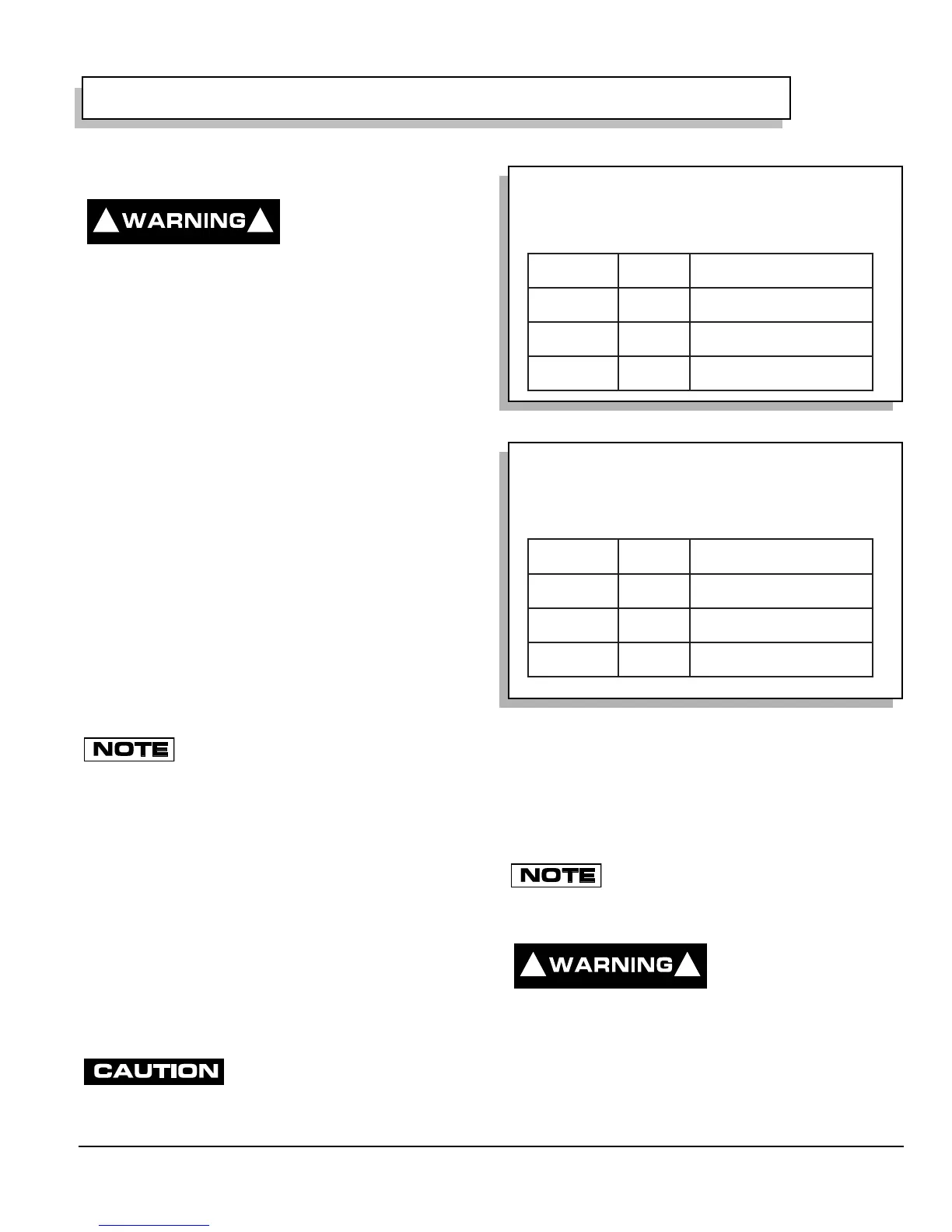
Installation is in the reverse order of removal. Tighten
motor terminal hardware to 66 in. lbs. (8 Nm) torque (Ref
Fig. 1 on page N-1)(Ref Fig. 2 on page N-1).
Install new cotter pins.
REAR AXLE DISASSEMBLY
The rear axle is a precision assembly,
and therefore any repair or replacement
of parts must be done with extreme care in a clean environment.
Before attempting to perform any service on the axle, read and
understand all of the following text and illustrations before dis-
assembling the unit.
Handle all splines with extreme care.
Snap rings must be removed/installed with care to prevent dam-
age of bearings, seals and bearing bores.
It is recommended that whenever a bearing,
seal or ‘O’ ring is removed, it be replaced with a
new one regardless of mileage. Always wipe the seals and ‘O’
rings with a light oil before installing.
To reduce the possibility
of personal injury, follow
the lifting procedure in
SAFETY section of this manual. Place wheel chocks
in front and behind the front wheels and check the
stability of the vehicle on the jack stands before start-
ing any repair procedure. Never work on a vehicle that
is supported by a jack alone.
! !
Fig. 1 Motor Wiring - 36 Volt
Fig. 2 Motor Wiring - 48 Volt
MOTOR
TERMINAL
WIRE
MARKER
FROM
A1
A2
S1
S2
A1
A2
S1
S2
Direction Selector "D"
Direction Selector "B"
Direction Selector "C"
Controller "M-"
36 VOLT MOTOR WIRING
MOTOR
TERMINAL
WIRE
MARKER
FROM
A1
A2
S1
S2
A1
A2
S1
S2
Direction Selector "D"
Direction Selector "B"
Controller "B+"
Controller "A2"
48 VOLT MOTOR WIRING
! !
 Loading...


