COMPONENT MAINTENANCE
MANUAL
UXF-35 LIFE PRESERVER, Part No. P01202-1XX
Page 8
May 28/14
25-60-35
(a) CO
2
Inflation Assembly
The CO
2
inflation system consists of a 33 gram CO
2
cylinder attached
to an inflator mechanism. Upon actuation, the compressed CO
2
gas
is released and fills the buoyancy cell.
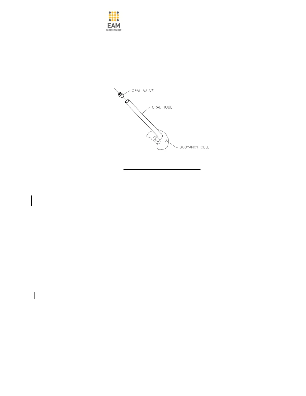
ORAL INFLATION SYSTEM
Figure 7
(b) Oral Tube Inflation Assembly
The oral tube inflation system consists of a 4.5 or 6 inch long tube
connected at one end to the buoyancy cell, with the other end fitted
with an oral valve. Inflation is achieved by blowing air, by mouth, into
the tube to either fill or top-off the buoyancy tube. The oral valve
serves to allow air to flow into and not out of the buoyancy cell.
(3) Harness Assembly
The UXF-35 life preserver uses a harness strap to secure the vest to the
wearer. The harness utilizes a 1” wide by 56” long belt strap webbing with
a set of plastic buckle fasteners. The UXF-35 is packed with the buckles
disengaged for quick donning.
(4) Light System Assembly
The UXF-35 series life preserver has a FAA TSO-C85 or C85a approved
water activated battery powered light system assembly. The light system
assembly consists of a lamp connected to a battery by a wire. The battery
is fastened to the harness assembly on the front of the vest and the lamp is
fitted to the vest placing it near the shoulder of the wearer.
The battery is activated when water enters into the battery through
openings on the battery case. Normal battery life for illumination is a
minimum of eight hours.
 Loading...