Page vi I.B. 3A74792H08
Effective 09/2014
FIGURES
Figure Title Page
3-8 Typical VCP-W 38kV Escutcheon ............................................................................................................. 16
4-1 Type VCP-W Circuit Breaker Manual Charging Handle in Use ................................................................ 18
4-2 Drawout Circuit Breaker (Bottom View) ..................................................................................................... 20
5-1 Rear View Showing Pole Unit Enclosure (VCP-W Only) ........................................................................... 21
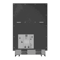
5-2 Plate Over Rear Truck Opening 2000A Breakers and Above (VCP-W Shown) ....................................... 21
5-3 Graphic Representation of Arc Interruption ............................................................................................... 22
5-4 Closing Cam and Trip Linkage .................................................................................................................. 24
5-5 Charging Schematic .................................................................................................................................. 26
5-6 Typical VCP-W “DC” and “AC” Control Schematics (Drawout) ................................................................. 27
5-7 Typical VCP-WR “DC” and “AC” Control Schematics (Fixed) ................................................................... 28
5-8 Secondary Plug Shown Mounted Lower Left Drawout Circuit Breaker ..................................................... 29
5-9 Secondary Terminal Blocks Shown Mounted Bottom Front Fixed Circuit Breaker ................................... 30
5-10 Undervoltage Trip Device Configuration .................................................................................................... 31
6-1 Lubrication Points (Drawout Circuit Breaker Shown) ................................................................................ 34
6-2 Rear Measurement for Contact Erosion Being Made (Circuit Breaker Closed) ........................................ 37
6-3 Graphical Representation of Contact Erosion Measurement .................................................................... 37
6-4 Side View of Loading Spring Indicator (Circuit Breaker Closed) ............................................................... 38
6-5 Graphical Representation of Contact Wipe Measurement of Loading Spring Indicator ............................ 38
6-6 Resistance Measurement Locations ......................................................................................................... 38
6-7 Status Indicators ........................................................................................................................................ 39
6-8 Starting Tape at Bottom ............................................................................................................................. 39
6-9 Wrapping Tape up around Cam ................................................................................................................ 39
6-10 Attaching Tape Around to Back of Cam .................................................................................................... 40
6-11 Attaching CloSure
TM
Test Tool at Hole “A” ................................................................................................ 40
6-12 Attaching CloSure
TM
Test Tool at H Pole “B” ............................................................................................. 40
6-13 Manually Charging Closing Springs .......................................................................................................... 40
6-14 Manually Closing Circuit Breaker with Marker in Hole “C” ........................................................................ 41
6-15 Top View of Cam and Marker Interface ..................................................................................................... 41
6-16 Move Marker 15° to Right .......................................................................................................................... 41
6-17 Move Marker 15° to Left ............................................................................................................................ 41
6-18 Remove Marked Masking Tape from Cam ................................................................................................ 41
6-19 Place Tape on Right Side Panel of Breaker .............................................................................................. 41
6-20 Illustrative Testing Tape Sample ............................................................................................................... 42
6-21 Front View of CloSure
TM
Tool Showing Mounting/Testing Hole Locations ................................................ 42
6-22 Typical Circuit Breaker Front View with CloSure
TM
Tool Attached ............................................................ 42
TABLES
Table Title Page
1-1 Type VCP-W Ratings on Symmetrical Current Rating Basis ...................................................................... 2
1-2 Type VCP-WC Ratings on Symmetrical Current Rating Basis ................................................................... 4
3-1 Approximate Circuit Breaker Weights ........................................................................................................ 11
5-1 Circuit Breaker Timing ............................................................................................................................... 29
6-1 Torque Guidelines ..................................................................................................................................... 33
6-2 Test Voltage ............................................................................................................................................... 36
6-3 CloSure
TM
Tool Mounting /Testing Locations by Circuit Breaker Type ..................................................... 42
6-4 Approximate Resistance Measurements ................................................................................................... 43
7-1 Recommended Renewal Parts for ANSI Rated Breakers ......................................................................... 46

 Loading...