This document provides comprehensive service information for Eaton Models 70422 and 70423 Pressure or Pressure-Flow Compensated Piston Pumps. It includes step-by-step instructions for complete disassembly, inspection, and reassembly, along with recommendations for successful repairs.
Function Description
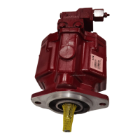
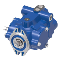
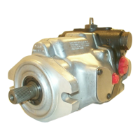
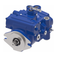
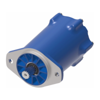
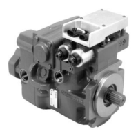
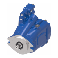
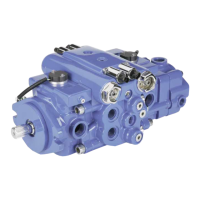
The Eaton Medium Duty Piston Pump is designed for hydraulic systems requiring pressure or pressure-flow compensation. It is available in two main models:
- Model 70422 or 70452: Offers a displacement of 0 - 38 cm³/r [0 - 2.32 in³/r].
- Model 70423 or 70453: Offers a displacement of 0 - 45 cm³/r [0 - 2.77 in³/r].
The pump's operation involves a rotating kit assembly, a camplate, and a compensator assembly that regulates pressure and flow. The document details the various components, including drive shafts, backplate assemblies, housing assemblies, and compensator assemblies, each with specific part numbers and descriptions.
Important Technical Specifications
Identification Numbers:
Pumps are stamped on the mounting flange with product number, rotation (L for Left Hand/CCW, R for Right Hand/CW), and a sequential numbering.
- Product Number Description:
- 70422 = Single Piston Pump
- 70452 = Single Piston Pump, w/ Aux. Flange
- 70423 = Single Piston Pump
- 70453 = Single Piston Pump, w/ Aux. Flange
- Serial Number Code: Includes revision level of parts list, last two digits of year built, day of month, and month. For units prior to Jan. 1992, it includes year manufactured, change code, and week of year.
Displacement:
- Model 70422/70452: 0 - 38 cm³/r [0 - 2.32 in³/r]
- Model 70423/70453: 0 - 45 cm³/r [0 - 2.77 in³/r]
Mounting Kits:
- K2 (Gear Pump Mounting Kit for "A" SAE flange): Part No. 70442-929, includes O-ring (1.59 mm Dia. x 82.55 mm ID.), washers, and cap screws.
- K3 (Cover Plate Kit for "A" SAE flange): Part No. 70142-915, includes O-ring (1.59 mm Dia. x 82.55 mm ID.), cover plate, and cap screws.
- K6 (Cover Plate Kit for "B" SAE flange): Part No. 990596-000, includes gasket, cover plate, cap screws, and lock washer.
- K7 (Gear Pump Mounting Kit for "B" SAE flange): Part No. 70453-901, includes coupler (41 Tooth), O-ring (1.59 mm Dia. x 101.6 mm ID.), lock ring, and cap screws.
Compensator Assemblies:
- Pressure-Flow Compensator (Non-Set):
- 70422-HU (Lefthand CCW Pump Rotation)
- 70422-HY (Righthand CW Pump Rotation)
- Pressure Compensator (Non-Set):
- 70422-HR (Fits Both Pump Rotations)
- Standard Factory Compensator Pressure Settings:
- Pressure compensator: 3000 to 3100 PSI (Optional: 1500 min. to 3100 max. PSI)
- Flow compensator: 190 to 210 PSI (Optional: 190 min. to 450 max. PSI)
Recommended Gauges:
- Inlet vacuum gauge: 2 bar to 1 bar [30 PSI to 30 inHg]
- System pressure gauge: 700 bar [10,000 PSI]
- Case pressure gauge: 0 to 25 bar [0 to 300 PSI]
Usage Features
The manual provides detailed diagrams and parts lists for various configurations, including:
- Drive Shaft Identification: Illustrates different drive shaft types (e.g., 13 Tooth, 15 Tooth, keyed, with retaining ring groove) and their compatibility with 2-bolt A or B flange backplates.
- Backplate Assembly: Shows different porting options (Rear Porting, Opposite Side Porting) and flange types (2-Bolt A Flange, 2-Bolt B Flange) for both 70422 and 70423 models, indicating left-hand (CCW) and right-hand (CW) rotations.
- Housing Identification: Specifies "A," "B," and "C" drain ports with .5625-18 SAE Straight Thd.
- Rotating Kit Assembly: Details components like piston assembly, spider, spider pivot, retainer, piston block, pins, washers, spring, and retaining ring.
Maintenance Features
General Recommendations for Repairs:
- Remove the pump from the application.
- Maintain extreme cleanliness; work in a clean area.
- Thoroughly clean port areas before disconnecting hydraulic lines.
- Plug pump ports and cover open hydraulic lines immediately after disconnection.
- Drain oil and clean the exterior of the pump before repairs.
- Wash all metal parts in clean solvent and dry with filtered, moisture-free compressed air (do not use paper towels or cloth).
- Always use new seals during reassembly.
- Lubricate new rubber seals with petroleum jelly (Vaseline) before installation.
- Torque all bolts over gasketed joints, then repeat the torquing sequence for gasket compression.
- Verify pump repair accuracy on an authorized test stand.
Tools Required:
- 9/16 Inch Socket
- 1-1/8 Inch End Wrench
- 11/16 Inch End Wrench
- Rachet Wrench
- Torque Wrench (100 lb./ft.)
- 3/16 Inch Hex Key (Allen)
- 3/16 Inch Hex Key (Allen Socket)
- Soft Face Hammer
- Internal Retaining Pliers (Straight .070 Tip)
- External Retaining Pliers (Straight .070 Tip)
- Regular or Locking Pliers
- Seal Driver or Similar Tool
- Petroleum Jelly (Such as Vaseline)
- 3/8 inch I.D. x 1-1/8 inch O.D. flat washer (2 ea.)
- 3/8 inch x 3-1/4 inch N.C. Cap screw (1 ea.)
- 3/8 inch N.C. Nut
Disassembly Instructions:
- Clamp drive shaft in a protected jaw vise.
- Remove allen head screws holding compensator, then remove compensator assembly, O-ring, and gasket.
- Remove cap screws from backplate, then loosen and remove backplate and gasket.
- Remove control piston and plug from backplate.
- Slide rotating assembly off shaft (pistons may not come out with piston block).
- Disassemble pistons, spider, and spider pivot from piston block.
- Piston block disassembly (internal pins or spring) requires specific tools: 2 ea. 3/8 I.D. x 1-1/8 O.D. flat washers, 1 ea. 3/8 x 3-1/4 N.C. cap screw, and 1 ea. 3/8 N.C. nut. Instructions are provided for compressing the spring to remove the internal snap ring.
- Remove retaining ring to free shaft seal and shaft.
- Remove shaft from housing by tapping with a wooden or plastic mallet.
- Remove shaft seal, washer, retaining rings, thrust washers, and bearing from shaft.
- Remove camplate from housing by removing internal retaining rings, covers, O-rings, inner races, and bearings.
- Remove spring collar and spring. Do not remove button and roll pin unless worn.
- Disassemble pressure-flow compensator assembly for cleaning and inspection.
- Remove and replace all shaft seals, O-rings, and gaskets with new items upon reassembly.
Inspection for Wear:
- Backplate (2): Inspect flat surface for smoothness, absence of grooves. Piston guide should be tight, needle bearing free of excessive play and in cage. Replace complete assembly if wear is present.
- Piston Block (5): Surface contacting backplate should be smooth and free of grooves.
- Pistons (5-1): Should move freely in bore; examine for scoring or contamination. O.D. should be free of wear or deep scratches. Shoes should be snug fit on ball end, flat and smooth (do not lap).
- Spider (5-2): Should be flat, no cracks, no wear in pivot area.
- Pivot (5-3): Should be smooth and free of wear.
- Camplate (6): Inspect polished shoe surface for scoring.
- Shaft (1): Inspect for wear in bearing and spline areas.
- Thrust Bearing (15) & Thrust Washers (16): Inspect for wear.
- Needle Bearing in Housing (3): Needles should be free of excessive play and remain in cage (no replacement needed if satisfactory).
- Compensator Springs (4-4 & 4-14): Inspect for breakage or weakness.
- Spools (4-2 & 4-12): Inspect for scoring.
- O-rings, retaining rings, gaskets, shaft seal should be replaced as new items from the seal repair kit.
Reassembly Instructions:
- Clean all parts with solvent and lubricate critical moving parts.
- Install camplate control spring (18) and spring collar (22) in housing (3).
- Insert camplate (6) into housing (3). Insert needle bearings (25) and bearing inner race (19) over camplate arms and slide into housing (3). Numbered end of bearing outward, chamfered I.D. of race inward.
- Install new O-ring (26) around O.D. of camplate pivot bearing (25). Install trunnion covers (20) and secure with retaining rings (11).
- Install retaining ring (10) on shaft (1). Install thrust washer (16), thrust bearing (15), and second thrust washer (16). Secure with second retaining ring (10).
- Install shaft (1) in housing (3) and install washer (13), shaft seal (17), and retain with retaining ring (12). Ensure retaining ring is seated.
- If piston block assembly was disassembled: compress pin keeper (5-4) and install in spline area of piston block. Install three pins (5-6) with head end inside block, in special grooves of piston block spline.
- Install washer (5-7), spring (5-8), and second washer (5-7) in piston block. Use 3/8 I.D. washers and 3/8 x 3-1/4 cap screw to compress spring and retain with retaining ring (5-9). Remove cap screw and washers.
- Install pivot (5-3), spider (5-2), and piston assemblies (5-1) in piston block. Install this assembly in housing, ensuring piston shoes contact camplate.
- Clamp assembly in protected jaw vise with open end of housing (3) up.
- Install new gasket (21).
- Install control piston (7) and plug (2-2) with new O-ring onto backplate, noting roll pin (3-2) locations.
- Install backplate (2) and retain with cap screws (27). Torque to 37 to 42 N-m [27 to 31 lb-ft].
- Install new O-ring (4-19-1) on plug (4-19). Install plug assembly, flow compensator spool (4-12), spring pivot (4-13), spring (4-14), flow spring follower (4-16) with new O-ring (4-15), and flow adjustment cap (4-18) with new O-ring (4-17) into compensator housing (4-1). Torque plug (4-19) 8 to 11 N-m [6 to 8 lb-ft] and flow adjustment cap (4-18) 14 to 16 N-m [10 to 12 lb-ft].
- Install new O-ring (4-19-1) on plug (4-19). Install plug assembly, pressure compensator spool (4-2), spring pivot (4-3), spring (4-4), pressure spring follower (4-6) with new O-ring (4-5), and pressure adjustment cap (4-8) with new O-ring (4-7) into compensator housing (4-1). Torque plug (4-19) 8 to 10 N-m [6 to 8 lb-ft] and pressure adjustment cap (4-18) 47 to 54 N-m [35 to 40 lb-ft].
- Install new gasket (24) and new O-ring (28), then install compensator assembly (4), and retain with four allen head cap screws (14). Torque to 14 to 16 N-m [10 to 12 lb-ft].
- Plug ports to preserve cleanliness until installation on vehicle.
Start-up Procedure:
- Ensure pump is properly installed and all hydraulic connections are tight.
- Fill pump housing at least 1/2 full with system oil filtered through a 10 micron filter.
- Fill reservoir with approved oil filtered through a 10 micron filter. Leave filler cap loose.
- For gasoline/L.P. engines: remove coil wire and turn engine over for 15 seconds. For diesel engines: shut off fuel flow and turn engine over for 15 seconds. This primes the pump.
- Disconnect sensor line from pump compensator and pull one valve spool while engine turns over to purge air. Reconnect after steady oil flow.
- Replace coil wire or return fuel flow. Start engine at low idle for one minute. Pump should pick up oil and go into low pressure standby within 30 seconds.
- Operate control valve and steering slowly without load to purge air and fill cylinders.
- Check and refill fluid level at reservoir.
- Check and tighten all line connections for leaks.
- Machine is ready for operation.
- Filter Changes: Recommended short hour filter changes for the first two changes after start-up (3-5 hours, then 50 hours). Follow routine scheduled filter changes for maximum hydraulic system life.
Fault - Logic Troubleshooting:
- A diagnostic aid for locating pump problems.
- Includes flowcharts for symptoms like "System will not Develop Proper Pressure or Flow" and "Pump Noisy or Overheating."
- Action steps include checking oil level, hydraulic fluid specs, inlet screen/strainer, compensator signal, and pump compensator.
- Comments provide details for each action step, such as filling to proper level, consulting owner's manual for fluid type, inspecting for plugged/collapsed lines, and checking for misadjusted/stuck/weak compensator components.