EasyManua.ls Logo

Eaton 70523 - User Manual

Eaton 70523
20 pages
Print Icon
To Next Page IconTo Next Page
Loading...
Parts and Repair
Information
Eaton
®
Medium Duty Piston Pump
Model 70523 or 70553, 0 -69 cm
3
/r [0-4.21 in
3
/r] Displacement
Pressure or Pressure-Flow Compensated Piston Pumps
No. 6-617
January 1998
Question and Answer IconNeed help?

Do you have a question about the Eaton 70523 and is the answer not in the manual?

Summary

Introduction

Identification and Tools Required

Parts Drawing

Parts List

Mounting Kits

Lists specific mounting kits for various SAE flange types.

Seal Repair Kit

Details the single seal repair kit for pump maintenance.

Item 1 - Drive Shaft Identification

Item 2 - Backplate Assembly

Item 4 - Compensator Assembly

Item 4 - Compensator Parts List

Item 3 - Housing Identification

Item 5 - Rotating Kit Assembly

Mounting Kits

Product Number

Repair Information

Disassembly

Step-by-step instructions for pump disassembly procedures.

Inspect Parts For Wear

Guidelines for inspecting pump components for wear and damage.

Reassembly

Detailed steps for reassembling the pump after inspection or repair.

Start-up Procedure

Fault - Logic Troubleshooting

Recommended Gauge Locations

Diagram and explanation of gauge placement for troubleshooting.

Diagram Action Step Comments

Explanations for steps within fault-logic troubleshooting diagrams.

Overview

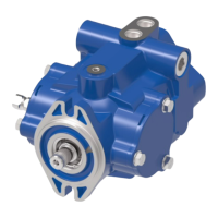
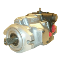
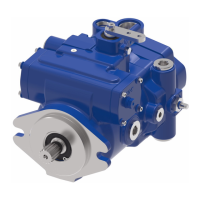
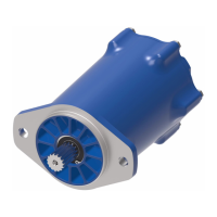
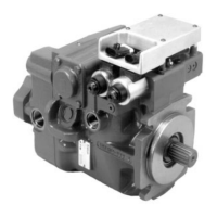
This document provides comprehensive service information for the Eaton Models 70523 and 70553 Medium Duty Piston Pumps. These are pressure or pressure-flow compensated piston pumps with a displacement of 0-69 cm³/r [0-4.21 in³/r]. The manual, identified as No. 6-617 and dated January 1998, outlines step-by-step instructions for complete disassembly, inspection, and reassembly, along with troubleshooting guidance.

Function Description:

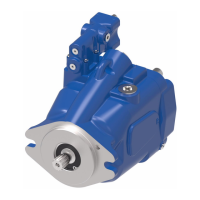
The Eaton 70523 and 70553 piston pumps are designed to provide hydraulic power in medium-duty applications. They feature either pressure compensation or pressure-flow compensation, allowing them to maintain a set pressure or a combination of pressure and flow, respectively, regardless of changes in system load. This compensation mechanism ensures efficient operation and protects the hydraulic system from overpressure. The pumps are available in both left-hand (counter-clockwise, CCW) and right-hand (clockwise, CW) rotation configurations, as viewed from the input shaft end. The 70553 model includes an auxiliary flange for additional functionality.

Important Technical Specifications:

  • Displacement: 0-69 cm³/r [0-4.21 in³/r].
  • Models: 70523 (Single Piston Pump) and 70553 (Single Piston Pump with Auxiliary Flange).
  • Compensation Types: Pressure Compensated or Pressure-Flow Compensated.
  • Rotation: Left-Hand (CCW) or Right-Hand (CW).
  • Drive Shafts: Various configurations including 14-tooth splined shafts and 31.8 [1.25] Dia. Keyed shafts, with corresponding output drives of 9-tooth external or 13-tooth external, depending on the backplate used (2-bolt A Flange or 2-bolt B Flange).
  • Housing Identification: Housing assemblies (Item 3) are identified by part numbers like 70500-303 (B Port), 70500-311 (A Port), and 70500-332 (A, B Ports). Drain ports are .875-14 SAE Straight Thd.
  • Compensator Assemblies:
    • Pressure-Flow Compensator: 70523-FW (Lefthand Rotation) and 70523-FU (Righthand Rotation).
    • Pressure Compensator: 70523-FT (For Both Pump Rotations).
  • Standard Factory Compensator Pressure Settings:
    • Pressure Compensator: 3000 to 3100 PSI (Optional settings: 1500 min. to 3100 max. PSI).
    • Flow Compensator: 190 to 210 PSI (Optional settings: 190 min. to 450 max. PSI).
  • Mounting Kits:
    • K2: Gear Pump Mounting Kit (for "A" SAE flanges).
    • K3: Cover Plate Kit (for "A" SAE flange).
    • K6: Cover Plate Kit (for "B" SAE flange).
  • Seal Repair Kit: 70523-900.
  • Recommended Gauges for Troubleshooting:
    • Inlet vacuum gauge: 2 bar to 1 bar [30 PSI to 30 inHg].
    • System pressure gauge: 700 bar [10,000 PSI].
    • Case pressure gauge: 0 to 25 bar [0 to 300 PSI].

Usage Features:

The pumps are identified by a product number (e.g., 70523-RAA), rotation (L for left-hand/CCW, R for right-hand/CW), and a sequential numbering. Serial number codes provide detailed manufacturing information, including revision level, year built, month, day, and testers' initials. This detailed identification system aids in accurate parts ordering and service. The manual provides product numbers for various configurations, including different drive shafts, backplate assemblies, housing assemblies, and compensator assemblies, catering to diverse application requirements.

Maintenance Features:

The manual emphasizes cleanliness as paramount during repairs. Key recommendations include:

  • Removing the pump from the application and thoroughly cleaning port areas before disconnection.
  • Plugging pump ports and covering hydraulic lines immediately after disconnection.
  • Draining oil and cleaning the pump exterior before repairs.
  • Washing all metal parts in clean solvent and drying with filtered, moisture-free compressed air.
  • Always using new seals during reassembly and lubricating new rubber seals with petroleum jelly (Vaseline).
  • Torquing all bolts over gasketed joints, then repeating the sequence for gasket compression.
  • Verifying repair accuracy on an authorized test stand.

Disassembly and Reassembly:

Detailed instructions are provided for disassembling components such as the compensator assembly, backplate, rotating assembly, drive shaft, and camplate. Specific warnings are given, such as not removing adjusting screw covers (which may void warranty) and the need to compress the piston block spring before removing its snap ring. Special tools like internal and external retaining pliers, a seal driver, and various wrenches are listed. Reassembly instructions guide the user through installing components in the correct order, applying new seals and gaskets, and torquing bolts to specified values.

Inspection:

The manual outlines critical inspection points for wear and damage:

  • Backplate (2): Inspect for smooth, groove-free surface, tight piston guide, and excessive play in the needle bearing.
  • Piston Block (5): Check for smooth, groove-free surface and free movement of pistons (5-1) in their bores.
  • Pistons (5-1): Examine O.D. for wear or scratches, and ensure shoes are a snug fit and flat. Do not lap piston shoes.
  • Spider (5-2) and Pivot (5-3): Inspect for flatness, cracks, and signs of wear.
  • Camplate (6): Check the polished shoe surface for scoring.
  • Shaft (1): Inspect for wear in bearing and spline areas.
  • Thrust Bearing (15) and Thrust Washers (16): Inspect for wear.
  • Housing Assembly (3): Check needle bearing for excessive play.
  • Compensator Springs (4-4, 4-14): Inspect for breakage or weakness.
  • Spools (4-2, 4-12): Inspect for scoring.
  • All O-rings, retaining rings, gaskets, and shaft seals should be replaced as new items from the seal repair kit.

Start-up Procedure:

A crucial start-up procedure is provided for rebuilt load sensing systems to prevent pump damage. This includes:

  • Ensuring proper installation and tight hydraulic connections.
  • Filling the pump housing and reservoir with filtered 10-micron system oil.
  • Leaving the reservoir filler cap loose to allow air to escape.
  • Purging air from the pump and sensor line by turning the engine over without ignition/fuel and manipulating valve spools.
  • Starting the engine at low idle speed and running for one minute, ensuring the pump picks up oil and enters low-pressure standby.
  • Operating control valves and steering to purge air from the system and fill cylinders.
  • Checking fluid levels and line connections for leaks.
  • Recommending short-hour filter changes (3-5 hours, then 50 hours) after placing the machine back into operation.

Fault - Logic Troubleshooting:

A diagnostic aid with explanatory diagrams helps locate pump problems. It guides users to match symptoms with problem statements and follow action steps (inspect, repair, or replace). Common symptoms addressed include "System will not Develop Proper Pressure or Flow" and "Pump Noisy or Overheating." Troubleshooting steps involve checking oil level, hydraulic fluid specifications, inlet screen/strainer, compensator signal, and the pump compensator itself (for misadjusted settings, stuck spools, or weak springs). Recommended gauge locations are provided for load sensing pressure, system pressure, inlet vacuum, and case pressure.

Eaton 70523 Specifications

General IconGeneral
BrandEaton
Model70523
CategoryWater Pump
LanguageEnglish

Related product manuals