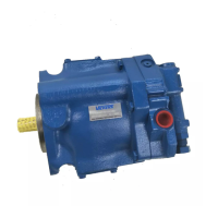
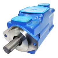
The Vickers Quiet Intra-Vane Single Pumps, specifically the 25V(T)-35V(T)-45V(T) Series (20 Design 282/283 Series), are hydraulic vane pumps designed for reduced noise levels while maintaining reliability and operating characteristics comparable to previous models. These pumps are part of the Eaton Vickers product line and are intended for industrial applications.
Function Description
The core function of these pumps is to convert mechanical energy into hydraulic energy by displacing fluid. The operating principle involves a slotted rotor splined to a drive shaft, which turns inside a cam ring. Vanes fitted into the rotor slots follow the inner surface of the cam ring as the rotor rotates, forming pumping chambers. Centrifugal force and pressure under the vanes hold them out against the cam ring. The 282/283 series pumps feature a balanced intra-vane design, where outlet pressure is continuously applied to a small intra-vane area of the vane. As the pump vane rotates through high and low quadrants, outlet pressure is alternately applied to the rest of the under-vane area. This varying pressure under the vane reduces wear and increases pump efficiency. Pump delivery can be modified by changing the ring or installing a new cartridge kit.
Important Technical Specifications
The pumps are available in various series: 25V, 25VT, 35V, 35VT, 45V, and 45VT. The "T" suffix indicates a thru-shaft model.
Key specifications derived from the model code breakdown include:
- Seals: Viton seals are an option (omitted if not required).
- Pump Series: Available in 25, 35, and 45 series.
- Pump Type: Quiet intra-vane type pump.
- Thru Shaft Connection Mounting: Available with SAE 2-bolt adapter flanges in "A", "B", or "C" flange sizes.
- SAE Rated Delivery (USgpm at 1200 RPM, 100 PSI):
- 25V: 12, 14, 17, 21 USgpm
- 35V: 25, 30, 35, 38 USgpm
- 45V: 42, 50, 60 USgpm
- Port Connections: SAE 4-bolt.
- Coupling: Specific couplings for SAE "A", "B", and "C" flanges with 30° involute splines and varying extensions (1.25, 1.75, 2.31 inches).
- Shaft Type: Straight key, splined, or heavy-duty straight key.
- Port Positions (Inlet cover positions viewed from cover end):
- A: Opposite outlet port
- B: 90° CW from outlet port
- C: Inline with outlet port
- D: 90° CCW from outlet port
- Design: 20 Design.
- Rotation (Viewed from shaft end): Left hand (L) or Right hand (omitted).
- Industrial Suffix: 282 (SAE 2-bolt mounting) or 283 (Foot mounted).
The sound reduction in the 282/283 series is achieved within the cartridge kit, which includes redesigned ring, vanes, rotor, and support plates. These pumps use 12 vanes, an increase from previous models that used 10 vanes.
Usage Features
- Direct Mounting: The pump features a pilot on the mounting flange to ensure correct mounting and shaft alignment. Care must be taken to firmly seat the pilot and avoid misalignment during screw tightening.
- Shaft Rotation: Pumps are assembled for either right-hand (clockwise) or left-hand (counterclockwise) shaft rotation, as viewed from the shaft end. Operating the pump in the wrong direction of rotation will cause seizure and expensive repairs.
- Piping and Tubing: All pipes and tubing must be thoroughly cleaned before installation. Minimizing flow resistance and leakage requires using only necessary fittings and connections. Tubing bends should be kept to a minimum (radius at least three times the inside diameter) to prevent excessive turbulence and friction.
- Hydraulic Fluid Recommendations: Fluid selection is critical for lubrication and power transmission. Recommendations are based on Vickers' industry experience, emphasizing cleanliness, continuous filtration, and proper reservoir design to prevent aeration.
- Sound Levels: While pump design contributes to noise reduction, fluid conditions significantly impact system noise. High viscosities at start-up can cause cavitation noise. Moderately high viscosity fluid can impede air release. Aerated fluid, caused by air ingestion through pipe joints, high-velocity discharge lines, cylinder rod packings, or fluid discharging above the reservoir level, can also lead to cavitation-like noise.
- Overload Protection: Relief valves are essential to limit system pressure to a prescribed maximum, protecting components from excessive pressure.
- Start-Up: The pump should prime almost immediately at a minimum drive speed of 600 RPM, provided air is initially purged from the system. Failure to prime quickly can lead to damage due to lack of lubrication. The inlet line must be filled with fluid and free of air leaks. Loosening an outlet fitting temporarily may be necessary to purge trapped air.
Maintenance Features
- Circuit Inspection: Regular inspection of fluid condition and connections is crucial. All hydraulic connections must be kept tight to prevent leaks and air ingestion. The reservoir should be checked periodically for contaminants, and the fluid should be drained and the reservoir cleaned if contaminated. Filter elements must be checked and replaced periodically to prevent clogging, which can lead to filtration loss. Air bubbles in the reservoir indicate a leak that needs to be sealed. Excessive heat or noise signals potential failure and requires immediate shutdown and correction.
- Adding Fluid: Hydraulic fluid must always be added through a clean wire screen (200 mesh or finer) or a 10-micron (absolute) filter to prevent contamination.
- Adjustments: No periodic adjustments are required other than maintaining proper shaft alignment.
- Lubrication: Internal lubrication is provided by the system fluid. Shaft coupling lubrication should follow manufacturer specifications. Shaft splines should be coated with a dry lubricant (e.g., Molycoat) to prevent wear.
- Replacement Parts: Only genuine Vickers parts should be used to ensure reliable operation. Repair kits are available and recommended for replacing commonly worn parts during overhaul.
- Product Life: Longevity depends on environment, duty cycle, operating parameters, and system cleanliness. Users must establish periodic maintenance to maximize life and detect potential component failure.
- Troubleshooting: A comprehensive troubleshooting chart is provided, listing common difficulties (excessive noise, overheating, system not developing pressure, loss of fluid), probable causes (low oil level, air in system, vacuum, thick oil, damaged seals, improper cartridge kit assembly, reversed lines, internal leakage, faulty heat exchanger, open relief valve, disconnected drive, ruptured lines), and corresponding remedies (fill reservoir, purge air, check lines, replace seals, reassemble kit, replumb lines, repair/replace components).
- Overhaul:
- Service Tools: Standard tools include torque wrenches, screwdrivers, internal retaining ring pliers, and hydraulic oil lubricant. An arbor press, ball peen hammer, and center punch may be needed for shaft bearing and key removal. A specific shaft seal driver is the only special tool required.
- Unit Removal: Before removal, all electrical power must be turned off, hydraulic pressure relieved, vertical cylinders lowered, and any load blocked. The hydraulic oil source should be closed off, the unit removed from the system, and all openings capped to prevent contamination.
- Disassembly: The pump exterior must be thoroughly cleaned. Mark the position of the cover and flange (on VT models) relative to the body. Remove mounting flange, key, and, for thru-shaft models, adapter flange, O-rings, spline coupling, and inlet cover. Remove the cartridge kit and its seals. Disassemble the cartridge kit according to sequence. Remove the spirolox ring, shaft group, washer, and drive out the shaft seal.
- Cleaning: All parts must be thoroughly cleaned with a commercial solvent compatible with the system fluid. Compressed air drying is not recommended unless filtered to remove water and contamination.
- Inspection, Repair, and Replacement: Check all internal passages for cleanliness and obstructions. Examine mating surfaces for nicks and burrs, and check locating pins, threaded parts, and retaining ring recesses for wear or damage. Minor burrs can be removed with an India stone. A complete cartridge kit should be installed if wear or scoring is noticed on the rotor, support plates, vanes, intra-vanes, or bushing. Check the bearing for wear, looseness, pitting, or cracks. Inspect the shaft for scoring and wear on seal and bushing mating surfaces.
- Assembly: Always replace old seals with new ones. Apply a light film of hydraulic fluid to all components. Install parts in reverse order of disassembly. Key steps include installing the shaft seal (spring facing inside), washer, bearing (if required), and shaft group. Carefully install the shaft group through the seal and secure it with the spirolox ring. Assemble the sealing ring and, if needed, a new cartridge kit. Ensure rotation arrows on the ring and rotor point in the correct direction, sharp edges of vanes lead in the direction of pump rotation, and O-rings and back-up rings are correctly positioned. Torque screws to specified values. Install the key and mount the pump.