For more information visit: www.eaton.com IB140012EN
Instructional Booklet
Page 10 Effective: March 2021
Operation and Maintenance Manual,
Automatic Transfer Switch Controller, ATC-900
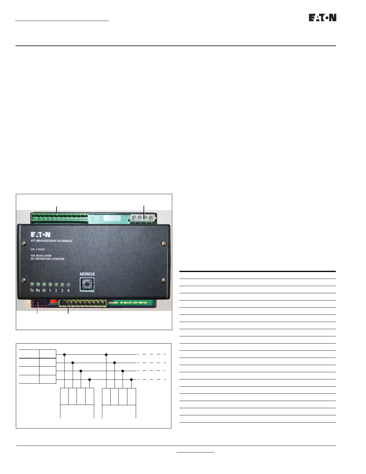
2.5 .2 I/O Module Description
The I/O Module is an extension of the ATC-900 controller's programmable inputs
and outputs. Each I/O Module has four inputs and four outputs. The inputs are
DC wetted (24 Volts at 10 ma) connections for various functional inputs. See
Figure 4 and Figure 5. Up to four modules can be used with the ATC-900 giving
the user up to 20 inputs or 20 outputs (including the controller's standard I/Os).
Depending on the options selected with the transfer switch, some of the I/Os
may be required to be fixed from the factory so that the user cannot change that
particular input or output. An example may be for Service Entrance, where the
"Go To Neutral" must be a fixed input. The Fixed I/Os will usually be on the
ATC-900 controller's I/O pins (wired to a terminal block). See Table 8 in Section
5.5 for the Features that relate to the switch type. Section 5.5 will also have
instructions on how to set the I/O functions required for an application. The
module(s) are interfaced to the controller using 485 communications with the
address selected on the front of the unit. Each I/O Module requires 120
Vac for
power. The I/O Module's Control power on J1-1,2 and J1-3,4 for S1 and S2
respectively, must be electrically isolated from each other. Most transfer switch
configurations have the power connector already included in the harness for two
I/O Modules. If the ATC-900 is powered by 24 Vdc, and the power is removed
from the switch, the I/O module will not communicate to the ATC-900. A
warning will be shown on the ATC-900. If the ATC-900 is powered by 24Vdc,
keep in mind that the I/O modules are powered with 120VAC. If an input or
output is required when the 120VAC is not available, then those signals should
be installed on the ATC-900's I/Os. A 24VDC inverter could also be installed to
produce 120VAC. The I/O Module's dimensions are 4.41" wide x 5.74" long x
3.14" deep. A CAT V cable is used to hook the I/O modules (Figure 5).The input
contact provides a wetted 24 Vdc at 10 mA. The output relay contacts are rated
for 10 A, 1/3 HP @ 250 Vac. The DC rating is 10 A @24 Vdc.
Figure 4 . I/O Module Connections.
Figure 5 . I/O Module(s) Wiring.
2.5 .3 Ethernet Module Description
The Ethernet Communications Module is an optional accessory
that operates as a communicating device in conjunction with a the
ATC-900 via an Ethernet network. The Ethernet Module provides
Ethernet TCP/IP. The J12 connection will be utilized for the Ether-
net Module.
2.5.4 USB Port
Every ATC-900 transfer switch includes a front panel, NEMA 4X
rated, USB port for use in uploading/downloading set points and
historical data to a USB flash drive. The connector is on the device
panel and has a flip down cover. Setpoints can be preconfigured
and saved on the flash drive to reduce the time spent on-site for
commissioning. Setpoints can quickly be copied from one ATS
and uploaded to another. No laptop is required.
Downloading event data provides the ability to more thoroughly
analyze information using a PC. Data can be quickly e-mailed
when offsite troubleshooting support is required. See Section 7.1
for downloading event data.
2.5 .5 HMI Remote Annunciator and Controller (RAC)
The HMi Remote Annunciator and Controller is an optional acces-
sory that monitors and controls up to eight transfer switches on a
7” LCD touchscreen. It is compatible with either Modbus RTU or
Modbus TCP/IP protocols. A basic mimic bus for each transfer
switch displays source availability, source connected and pre-
ferred source. Users can drill down to metered source values and
event history for each transfer switch. Users can also change set-
points and do many of the functions remotely instead of being in
front of the switch. All control features are password protected
and include engine test, transfer to emergency (peak shaving),
manual retransfer and bypass time delays.
2.5.6 Connector Part Numbers
ATC-9 0 0 mating connectors (Plugs)
OUTPUTS (COM-NO-NC)
12-11-10 9-8-7 6-5-4 3-2-1
POWER (S1, S2)
COMMUNICATION
INPUTS
10 9-8 7-6 5-4 3-2 1
GND - IN4, IN3, IN2, IN1, Do not use
I/O Part#
70C1776G01
SHLD
CMN
A(-)
B(+)
ATC-900
J11
SHLD
CMN
A(-)
B(+)
SHLD
CMN
A(-)
B(+)
I/O MODULE
#1
I/O MODULE
#2
J3
#3
#4
CONNEC TOR
DESIGNATION # OF PINS CONNEC TOR PART#
J1 3 1268C07H41
J2 3 1268C07H41
J3 3 1268C07H41
J4 19 67A2590H25
J5 Internal use only 3 66A8190H01
J6 12 67A2590H32
J7 4 1268C07H31
J8 USB M22-USB-SA
J9 8 66A8190H04
J11 4 66A8190H02
J12 4 66A8190H02
J13 Internal use only 4 66A8190H02
J14 n/a from DCT Module
J15 6 66A8190H03
DCT Module
J18 2 66A8190H05
I/O Module
J1 120VAC Power 4 1268C07H31
J2 Inputs and GND 10 67A2590H28
J3 Communications 4 66A8190H02
J4 Outputs Form C 12 67A2590H32

 Loading...


